| Search | Login/Register
   Home » Melquiades Amplifier » Better chassis design for Melquiades. (5 posts, 1 page)
  Print Thread | 1st Post |  
Page 1 of 1 (5 items) Select Pages: 
08-25-2007 Post does not mapped to Knowledge Tree
Romy the Cat


Boston, MA
Posts 10,051
Joined on 05-28-2004

Post #: 1
Post ID: 5114
Reply to: 5114
Better chassis design for Melquiades.

 Jordi wrote:
If I build them ... I'm going to use different cases. Man, the one's shown are U-G-L-Y.

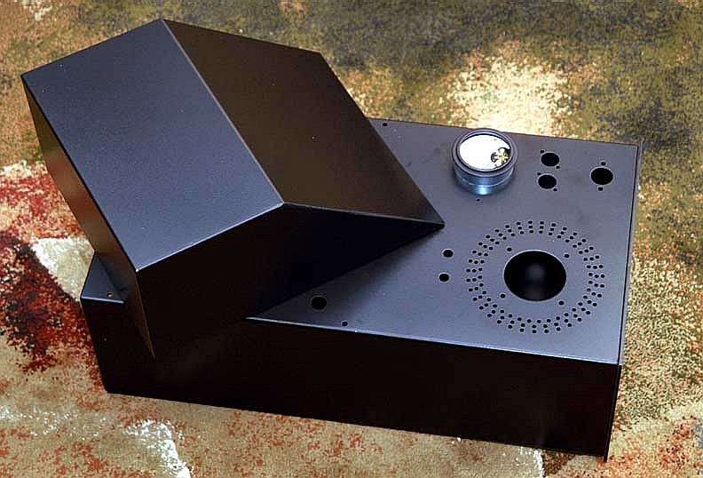
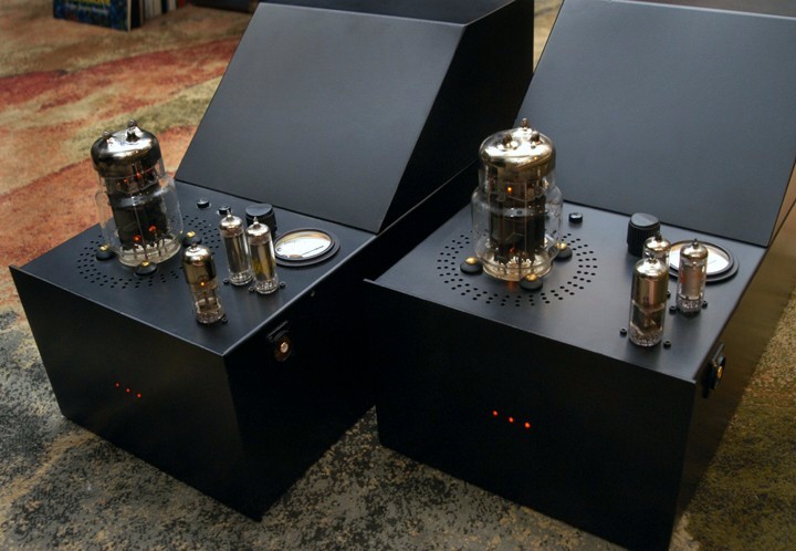
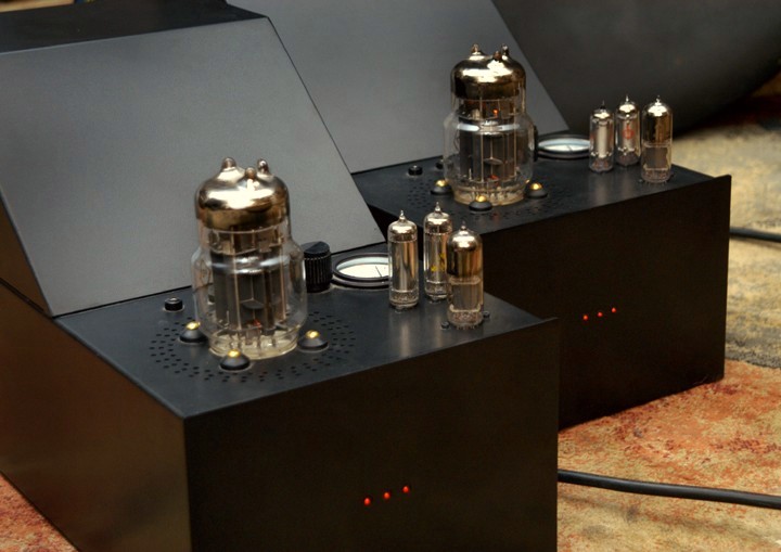
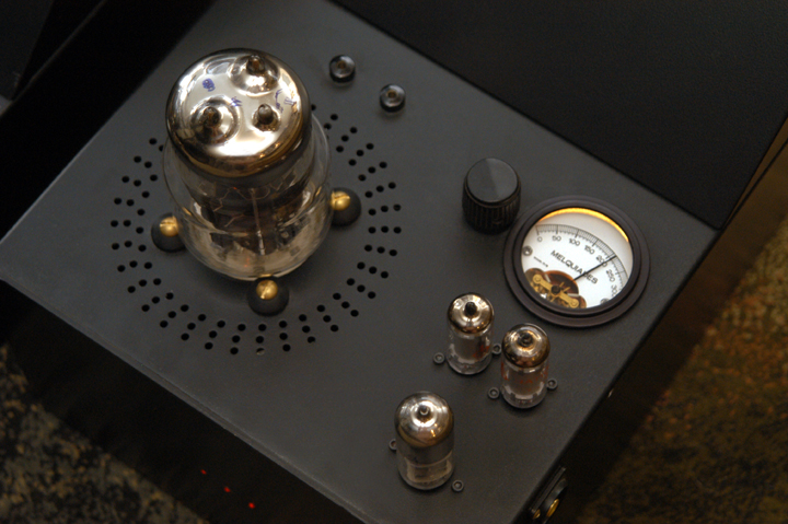
To my view the chassis for the full-range Melquiades is not ugly, in fact I do appreciate the design immensely, functionally and cosmetically. That chassis was very much not accident but a result of quite long thoughts process with objectives of better appearance and also with aim to optimize the currents passes… (It of cause might be better implemented if I money to the case-work but it was not my objective to make expensively looking amp. The case cost me around $200 and I feel that the fundamentals of the design are there. If I would be wiling to pay 1500 for the amp case then it will be the very same chassis layout.)

Still, the tastes are deferent and if someone willing to propose a better layout or at least better appearance of the two-stage amp then I very much would like you to propose what you envision. I will most likely not build any more full-range Melquiades – I have no use for a full range amp – but I still would like to expend my mind what might be more interesting for two-stage chassis. Also, if some other would go this direction then they might be benefited with your better case idea.

Rgs, Romy the Cat


"I wish I could score everything for horns." - Richard Wagner. "Our writing equipment takes part in the forming of our thoughts." - Friedrich Nietzsche
08-25-2007 Post does not mapped to Knowledge Tree
drdna
San Francisco, California
Posts 526
Joined on 10-29-2005

Post #: 2
Post ID: 5117
Reply to: 5114
Still planning
Ever since the Melquiades schematic was published, I have been planning to build one, because the objectives and topology seem like they would work for my system.  Unfortunately I am very much not a DIY person.  Even though I have built my own preamp, cables, revised my speakers, and built up a Welborne amp from a kit, I am pretty dissatisfied with the results.  Not that the sound is bad, but my technique must be bad.  Because sometimes during the day the sound will get really particularly bad, even to the point that it sounds like clouds are passing by over the music, if you understand what I mean. 

So I am kind of intimidated to build the Melquaides because I think I will probably just blow it up since I don't fully understand the electronics.

So when I think about the physical layout of the Melquiades, which I always thought looked quite utlilitarian, I wonder, what was the thinking behind putting the tube sockets and transformers etc. where they are.  I assume it was to minimize problems with the sound being corrupted by electromagnetic fields, but what was the thinking behind the design choices and compromises made? 

It would be instructive to understand this, and perhaps help me to feel comfortable to finally build this thing.

Adrian
08-25-2007 Post does not mapped to Knowledge Tree
drdna
San Francisco, California
Posts 526
Joined on 10-29-2005

Post #: 3
Post ID: 5118
Reply to: 5114
Updated schematic
Actually Romy, are you going to update the schematic to reflect the corrections? Adrian
08-25-2007 Post does not mapped to Knowledge Tree
Romy the Cat


Boston, MA
Posts 10,051
Joined on 05-28-2004

Post #: 4
Post ID: 5120
Reply to: 5117
The follow up to the layout…

 drdna wrote:
Not that the sound is bad, but my technique must be bad.  Because sometimes during the day the sound will get really particularly bad, even to the point that it sounds like clouds are passing by over the music, if you understand what I mean.

As I understand you are describing the problems with sound that are poorly electricity related.

 drdna wrote:
So I am kind of intimidated to build the Melquaides because I think I will probably just blow it up since I don't fully understand the electronics.
So do I. The beauty of Melquiades is that it is remarkably simple, and there is very little that might blow up in there. In fact even if something does blow up then it will happen very none-dramatic. If someone will built it and need help them I might publish a step by step instruction the will make the building it very secure and virtually imposable to make mistakes or incidents.

 drdna wrote:
So when I think about the physical layout of the Melquiades, which I always thought looked quite utlilitarian, I wonder, what was the thinking behind putting the tube sockets and transformers etc. where they are.  I assume it was to minimize problems with the sound being corrupted by electromagnetic fields, but what was the thinking behind the design choices and compromises made? 
1) The tube sockets are put in the way it is because I would like to create a straight and impediments-free transmission line for the signal. The signal enters in the side and immediately goes to bias resistor R5 and to the driver grid. The bias tubes are right at input as I did not what to run any long cables, particular from the negative gas tube. Right form the plate of the driver via straight C3 cup signal goes to the output tube and to the OPT that is located as close as possible (as heat would allow). After the OPT the signal is robust to go wherever it wishes. So, the signal path is very straight as short as the physical dimension of the parts allows. My obesities were for signal does not use any wires then the natural leads of the parts.

2) With power transformers and chokes I cared less about electromagnetic fields as I decided to put them outside of the main chassis under the angled bulge sort of a large transformer can. The chassis is thick steel, so it does very good shielding.  I have extra benefits to keep the transformer atop on the main chassis as I could put very effective and think sorbothane (1”) gaskets between the transformer and the main chassis.

 drdna wrote:
… are you going to update the schematic to reflect the corrections?

Actually there is not a lot to update there, unless you asked for a simplified version that I described earlier. The very few values the might be slightly adjusted be very simply offset during the calibration of the amp what it is done. I have another 3.3 version with changed indictor in the driver stage (with is not a big deal to begin with) but I have no good PDF rendering utility. Most PDF driver, inching the Adobe drivers, corrupt the images when they render Enterprise Visio files. I remember two years ago when I made the published version I went over a dose driver until I found a good on. I do not remember what it was…. Anyhow, I will find something and will update it soon on later…

The Cat


"I wish I could score everything for horns." - Richard Wagner. "Our writing equipment takes part in the forming of our thoughts." - Friedrich Nietzsche
08-25-2007 Post does not mapped to Knowledge Tree
Paul S
San Diego, California, USA
Posts 2,576
Joined on 10-12-2006

Post #: 5
Post ID: 5121
Reply to: 5117
Is "bad sound" worse on hot days???
Adrian, your bad sound may or may not be the result of poor mechanics on your part, however at this point I would put my money on the electricity as the likely suspect.

Not to say you couldn't improve on Romy's design, but I am guessing that his post-ML2 stuff is pretty well conceived and executed in terms of sound.

If you haven't done it lately, try listening in the early morning or late at night.

You might wind up less skittish about and spare yourself some grief by doing a +/- "stock" Milq...

Best regards,
Paul S
Page 1 of 1 (5 items) Select Pages: 
Home Page  |  Last 24Hours  | Search  |  SiteMap  | Questions or Problems | Copyright Note
The content of all messages within the Forums Copyright © by authors of the posts