Rerurn to Romy the Cat's Site
In the Forum: Melquiades Amplifier
In the Thread: Better chassis design for Melquiades.
Post Subject: The follow up to the layout…Posted by Romy the Cat on: 8/25/2007
 drdna wrote: drdna wrote: |
| Not that the sound is bad, but my technique must be bad. Because sometimes during the day the sound will get really particularly bad, even to the point that it sounds like clouds are passing by over the music, if you understand what I mean. |
|
As I understand you are describing the problems with sound that are poorly electricity related.
| drdna wrote: |
| So I am kind of intimidated to build the Melquaides because I think I will probably just blow it up since I don't fully understand the electronics. |
|
So do I. The beauty of Melquiades is that it is remarkably simple, and there is very little that might blow up in there. In fact even if something does blow up then it will happen very none-dramatic. If someone will built it and need help them I might publish a step by step instruction the will make the building it very secure and virtually imposable to make mistakes or incidents.
| drdna wrote: |
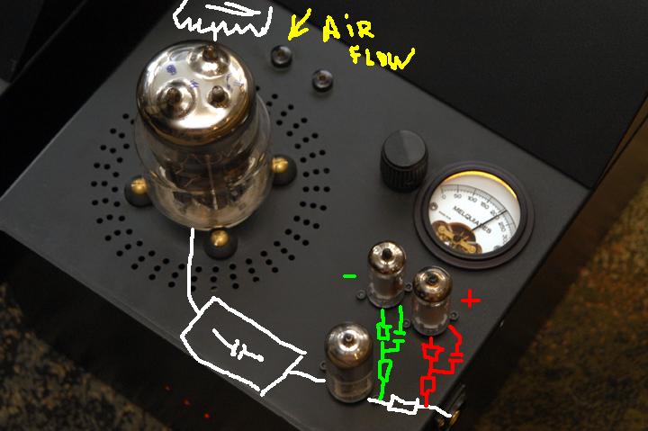
| So when I think about the physical layout of the Melquiades, which I always thought looked quite utlilitarian, I wonder, what was the thinking behind putting the tube sockets and transformers etc. where they are. I assume it was to minimize problems with the sound being corrupted by electromagnetic fields, but what was the thinking behind the design choices and compromises made? |
|
1) The tube sockets are put in the way it is because I would like to create a straight and impediments-free transmission line for the signal. The signal enters in the side and immediately goes to bias resistor R5 and to the driver grid. The bias tubes are right at input as I did not what to run any long cables, particular from the negative gas tube. Right form the plate of the driver via straight C3 cup signal goes to the output tube and to the OPT that is located as close as possible (as heat would allow). After the OPT the signal is robust to go wherever it wishes. So, the signal path is very straight as short as the physical dimension of the parts allows. My obesities were for signal does not use any wires then the natural leads of the parts.
2) With power transformers and chokes I cared less about electromagnetic fields as I decided to put them outside of the main chassis under the angled bulge sort of a large transformer can. The chassis is thick steel, so it does very good shielding. I have extra benefits to keep the transformer atop on the main chassis as I could put very effective and think sorbothane (1”) gaskets between the transformer and the main chassis.
| drdna wrote: |
| … are you going to update the schematic to reflect the corrections? |
|
Actually there is not a lot to update there, unless you asked for a simplified version that I described earlier. The very few values the might be slightly adjusted be very simply offset during the calibration of the amp what it is done. I have another 3.3 version with changed indictor in the driver stage (with is not a big deal to begin with) but I have no good PDF rendering utility. Most PDF driver, inching the Adobe drivers, corrupt the images when they render Enterprise Visio files. I remember two years ago when I made the published version I went over a dose driver until I found a good on. I do not remember what it was…. Anyhow, I will find something and will update it soon on later…
The CatRerurn to Romy the Cat's Site