| Search | Login/Register
   Home » Melquiades Amplifier » Bias help (97 posts, 5 pages)
  Print Thread | 1st Post |  
Page 4 of 4 (97 items) Select Pages:  « 1 2 3 4
   Target    Threads for related reading   Most recent post in related threads   Forum  Replies   Views   Started 
  »  New  Full range Melquiades implementation..  Solved...  Melquiades Amplifier  Forum     81  564468  02-23-2011
  »  New  Melquiades For Dummies™ - step by step...  Amp still open...  Melquiades Amplifier  Forum     28  213470  08-29-2007
  »  New  Building Melquiades: Chronicle of full-range..  VR2 issue leading to jump in current on 6C33 tube...  Melquiades Amplifier  Forum     44  433020  06-09-2006
08-19-2013 Post does not mapped to Knowledge Tree
Romy the Cat


Boston, MA
Posts 10,160
Joined on 05-28-2004

Post #: 76
Post ID: 19945
Reply to: 19943
Bais and filament voltages
fiogf49gjkf0d
DA, looks like very nice  and lucid assembly. How do you like the sound of the thing?

The  output stage 200mA /187V. It is a bit too small but I will do. I do not know what the gap you have in your OPT. If it is limited to 200mA then stay there, you might crack the voltage to 200V if you need a little bit power from your 6C33C.

The  driver stage 205v (test point A) and -4.3v bais – that is perfect.

The DC drift at inputs – that shall not be. Where the drifts come from? The gas tube shall stabilize both positive and negative voltages. Are you sure that your preamps do not drive DC? Also, what the drift you are talking about? If you have the voltage dancing around -0.5 to +0.5 mA then I would consider it normal and you will not be able to stabilize it further. Try to hand-connect the single signal wire to your input jack. You shall not be able to hear any clicks or any effect indication that you are connecting or disconnecting. Also, I see a volume control at your input. Make sure that it is has impedance that in each position of the volume control the bias voltage does not change. You might pull the positive gas tube out of socket and shot the inputs. Then run the volume control up and down – your bias voltage shall be stable. Do not forget that positive bias that you apply to the input is virtually a shorting or juts a way to balance out the output impedance of your preamp and to kill DC what the amp is not connected.

The bias lines around 175v is too low and 5.5 mA current is very low. The gas tubes do not provide good regulation what they are too soft loaded. In my estimation you need to drive 20-30mA across the gas tubes in order then to be more stable in operation and surprisingly to sound better. If your transformer give too little voltage for bias supply then you need to adjust the volume of the R15 and R16 resistors or perhaps the R11 and R12 in order to have on the B and C point around 190V- 195V.

You do need to find a way to set the filament voltage higher. Do you think the guys who did your transformers fuck it up? If so you can take it with them. You do need 6.3V and I would make them to adjust it. How do you drive your amp? If you use something like Pure Power or PS audio regenerator then you might set it to 125 instead of 115V or something like this. This would be a not kosher fix and I would go for transformer makers instead.
It is look to me that they underpowered your transformers both bias and filament and perhabs the output plate transformer.

The Cat


"I wish I could score everything for horns." - Richard Wagner. "Our writing equipment takes part in the forming of our thoughts." - Friedrich Nietzsche
08-19-2013 Post does not mapped to Knowledge Tree
DA
Posts 12
Joined on 04-10-2012

Post #: 77
Post ID: 19949
Reply to: 19945
Bais and filament voltage
fiogf49gjkf0d
Well, it looks like I got fucked by the transformer company.that realy sucks !!!  I have not talked to them yet ,but even if they agree to replace them it will take at least 6-8 weeks plus international shipping cost , import tax , VAT .

Filament transformer - if only the 6E5P is connected then I get 6.3v. Once I add the 6C33C voltage drops to 5.8 -5.9v.....
Bais transformer - only 415v instead of 440v...

How do you like the sound of the thing ?

Well can not comment on sound yet but it works (connected to a small monitor at my workshop ) sounds clean and nice...

The  output stage 200mA /187V. It is a bit too small but I will do. I do not know what the gap you have in your OPT. If it is limited to 200mA then stay there, you might crack the voltage to 200V if you need a little bit power from your 6C33C.

I use Lundhal 1627am /200mA  in D configuration . How to raise voltage if needed ? R22 ?
The DC drift at inputs – that shall not be

It is more then +- 0.5mV more like +- 2-3mV ,but I am not worried about it at this point.perhaps it has to do with the low current and voltage of gas tubes ?  If your transformer give too little voltage for bias supply then you need to adjust the volume of the R15 and R16 resistors or perhaps the R11 and R12 in order to have on the B and C point around 190V- 195V.  Replaced R15 and R16 but that did not work,even with 50 ohm resistors I only get 180v.
Anyway looks like the project is on hold for now and that (really) sucks.

Regards
Daniel
08-19-2013 Post does not mapped to Knowledge Tree
Romy the Cat


Boston, MA
Posts 10,160
Joined on 05-28-2004

Post #: 78
Post ID: 19950
Reply to: 19949
Go after transformers maker.
fiogf49gjkf0d
Well, they did not meet your specification, that is simple as that and they shall be taking care of all international shipping cost , import tax , VAT. I am a bit surprised as if it is more or less serious company then they shall not be able to miss the specs in this way. They clearly were trying to save money by making for you transformer with lover VA. What the scams, who those assholes are?

if you are with Lundhal 1627am /200mA  the n stay with your 180-190mA and run ~ 200-210V. That is if you need a full power. If you have very sensitive load to driver them you might not need it and might go for a half plate and use 150-160mA. The proper way to raise voltage of cause is by use of higher voltage transformer but if you do not have this option and if you use a very high volume of C10 then you might drop the volume of R22. If the C10 is too high then the C11 and R22 do not really do anything and you can bypass them. 200mA over 50R resistor will not give you too much voltage gain however.
 
The drift over +- 2-3mV is OK and it will go much better if you load your gas tubes harder – the gas tubes do not have good stability at 5mA. Still, if the 2-3mA are drifting very slow then it is not a big deal.
 
If you got screwed with transformer then there is some way to selvedge the project by introducing a very mild input capacitor before the input chokes. That will swing voltage higher but this also will/might have some sonic effect. I would not do it as you will always feel fucked and compromised.  I am sorry that the transformer situation had happened to you but I think you have very legitimate complain to the transformers maker.


"I wish I could score everything for horns." - Richard Wagner. "Our writing equipment takes part in the forming of our thoughts." - Friedrich Nietzsche
02-03-2014 Post does not mapped to Knowledge Tree
DA
Posts 12
Joined on 04-10-2012

Post #: 79
Post ID: 20517
Reply to: 19950
Update , bais and high pass
fiogf49gjkf0d
A little update on the Milq amp.After sorting  some of the problems with the amps transformers (see posts above ) .I now have two mono blocks operational that have about 700 hours ,I'm so glad hour meters were installed .

Filament voltage is spot on 6.3v.

Plate voltage is low 190V / 185 mA as I decided not to change it yet because I want to live with it for awhile and then try using half 6c33c .it is apparent that power is not an issue with my speakers and room size.

Bais lines are 197 v. Gas tubes draw about 10mA . Now here is my  first question - how to make them draw 20 - 25mA ? R11 R12 ?

The second question has to do with how to unload the Milq from low  frequency  < 60hz ? How to or where to install a low pass filter ?

As you can see I have not commented on the Milq sound and there are reasons for that,you see my system (and room ) are new and in the long process of building , assembling , tuning and more tuning .... All I can say is that is is possible that this is the last system I will build , yes it is that promising !

Some details on the speakers which are based on the Macondo Axioms.

Bass.  -                          old 15 " pioneer driver in sealed 110 liter box. Will be replaced
Upper bass  -                  125hz horn 4"throat  fane 8m
Lower mid fundamental -  220hz horn 4" throat wizerless lowther pm6a.  Experimental
Mid   -  410 hz horn.       JBL 2440 
High.  -                          not sure yet

Best regards
Daniel
02-04-2014 Post does not mapped to Knowledge Tree
DA
Posts 12
Joined on 04-10-2012

Post #: 80
Post ID: 20522
Reply to: 20517
Correction
fiogf49gjkf0d

DA wrote 
"The second question has to do with how to unload the Milq from low  frequency  < 60hz ? How to or where to install a low pass filter ? "


Correction-  it should read "How to or where to installation high pass filter ? "


Daniel 
02-04-2014 Post does not mapped to Knowledge Tree
decoud
United Kingdom
Posts 247
Joined on 03-01-2008

Post #: 81
Post ID: 20523
Reply to: 20522
Milq high pass
fiogf49gjkf0d
The coupling capacitor is a first order high pass filter. I have .68 in there for there for this purpose. Obviously the slope will be shallow, so precision in the value will not be critical.
02-04-2014 Post does not mapped to Knowledge Tree
Romy the Cat


Boston, MA
Posts 10,160
Joined on 05-28-2004

Post #: 82
Post ID: 20526
Reply to: 20523
Coupling capacitor
fiogf49gjkf0d
Daniel, if you have start, the igniting voltage, on the gas tubes 197V then it is perfect. If the tubes do maintain stable 150C then leave it as it. Each of the gas tribes has own stabilization voltage. If one of them has let say 148V and another 150.3V then you might have not enough turns in your adjustable resistor to set the input voltage to zero, So, juts change one of the gas tubes or switch them between each other. As you will set the gas tube and lock the operational parameter it will be good for many years.


The high pass filter for Milq is very simple. As “decoud” said the coupling capacitor is a first order high pass filter. Set it for whatever frequency you want. If you need sharper filter, let say second order then you can drop a coil from grid to ground, introducing another first order via RL filter. I would not do it and use just filter in coupling capacitor and if you need more than I would do it at speaker level, you do not run DSET and all your filtration at speaker level. The coupling capacitor filter will be nice to protect the OPT from any LF saturations.

Rgs, Romy


"I wish I could score everything for horns." - Richard Wagner. "Our writing equipment takes part in the forming of our thoughts." - Friedrich Nietzsche
04-03-2018 Post does not mapped to Knowledge Tree
G
Posts 8
Joined on 03-31-2018

Post #: 83
Post ID: 24790
Reply to: 20526
Bias

Hi Romy

I have built a Melq prototype and need some help with the bias.

This is my first tube amp build so my understanding is not great.

All parts values were used as per the 4.4 schematics. Rectifier bridges were built with Infineon SDT12S60 diodes. I was getting slightly less voltage on DC side however I’ve ordered my power transformers with multiple primary taps so I was able to adjust it.

My gas valves stabilise at 146.1v and 145.6v.

When I set 0v dc at the input via VR1 I get - 4.3v on the driver grid. The B+ on the first tube is 189v.

Should the grid bias voltage change when I adjust VR1? In my case it does – if I keep increasing dc on inputs I can get to -1.5v on the grid and around 60v on B+.

Everything seems ok but when I check the V1 voltage at B (146.1v) on the positive bias line the dc on the input suddenly jumps to ~0.47v, the grid voltage drops to -3.5v and B+ goes down to 160v. Now if I test the negative bias voltage at C everything goes back to how it was before.

The other thing is that when I switch the bias power off the dc on the inputs goes up to +20v.

The DC on the inputs also drifts ~+-50mV. 

Is there any difference which side legs you connect the VR1? I connected mine so I get 0 to 20k. If I was to connect it the other way round then I will get 0-5k-0.

Where should I take the measurement for the V1 current draw? Do I connect my multimeter in series between R11 leg and tube anode?

The amp is very quiet when I test it with my old ipod however if I connect it to my preamp or dac it’s noisy so I need to double check my grounding probably.

The output stage seems fine. I get ~202v/ ~195ma. ~-78v on bias. I use Lundahl ll1627 amorphous transformers wired in D. My fane 8m is 8r and s2 16r.

I tested the amp with midrange and upper bass and it sounded very promising. It’s very fast and harmonically rich.

In your correction thread you recommend: 12) Put two 10R, 5W resistors (in each leg) between the rectification bridges and secondary of the power transformers. Is this necessary with my bridges ? I haven't added them yet. 

Thanks!
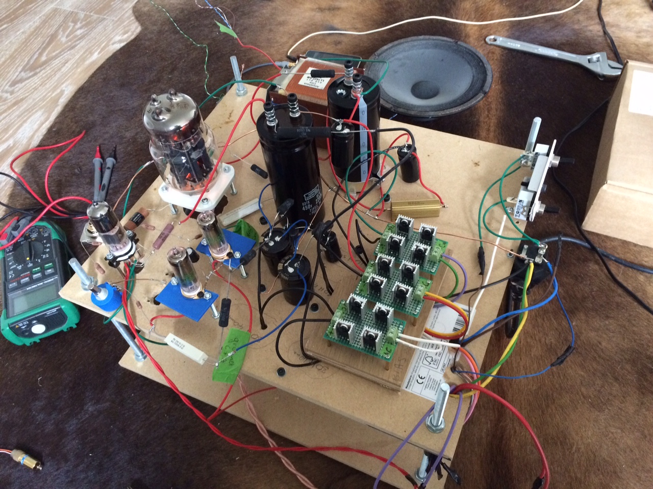
G_Melq.JPG

G_system (2).JPG
04-03-2018 Post does not mapped to Knowledge Tree
Romy the Cat


Boston, MA
Posts 10,160
Joined on 05-28-2004

Post #: 84
Post ID: 24791
Reply to: 24790
God, it was so long time ago!!!!
 G wrote:
Should the grid bias voltage change when I adjust VR1? In my case it does – if I keep increasing dc on inputs I can get to -1.5v on the grid and around 60v on B+.
   
Nope, it should not, well it is and it is not. Are you sure that you put the VR1 resistor in positive side of bias? Let me to explain. What I typically do to experiment is shorting the amp input and disconnect positive bias. The resistor R5 in this case acts as a bias resistor separating voltage between negative supply that goes the tube grid and ground. Let pretend that you have 4V on the driver grid while input is shorted. Now the certainly is balanced perfectly. If you un-short the amp input then bias will move but adding the positive supply on the left side of R5 resistor and setting 0V in there you introduce a virtual ground for the left side R5 and the bias in case you have  0V  at input should be identical to the  bias when the inputs are shorted. Under normal circumstances you would never adjust 0V at input, I did it one and over year is stays 0V. Even change of the driver tubes do not effect it. The only time you would need to do some adjustment would be what you change gas tubes as all of them stabilize slightly different voltage. Generally this topology might be recognized as “virtual battery”, where R5 resistors acts as voltage emitter because it has 0V on left and minus 4V on right.  Anyhow, if your bias voltage move too MUCH when you adjust VR1then there are two possibility:  
 
1)    You put the VR1 accidently on negative side, between R10 and C5, or somewhere in that negative supply.
2)    Your pream has very high output impedance.
   
Bothe on the case above are not good but they also are not bad. If you adjust 0V at input then you do not care about anything and you filter out all external factors.
 G wrote:
The DC on the inputs also drifts ~+-50mV. 

It should not be this way. If you say that it drifts ~+-5mV I would say that it is too high but let it to drift. The 50mV is too much. Switch the gas tubes, I think one of them are faulty. In case you use a direct coupled preamp make sure that it does not send any DC drift to its output.
 G wrote:
Is there any difference which side legs you connect the VR1? I connected mine so I get 0 to 20k. If I was to connect it the other way round then I will get 0-5k-0.

Sorry, I do not know what VR1 you use and I do not know the specific of it’s connection. You can use in there any good multi-turn in order to set 0V at input. If you have not enough turn to do so then slightly adjust R9 or R10. The better would be is to change the gas tubes, put positive to negative, or to get a different set all together.  They stabilize anywhere from 144V to 156V and a half volts of stabilization differences would reflect good 10K in VR1 resistor. Do not hold me responsible for exact numbers I juts pull it out of my ass now. Anyhow, flipping the tubes between the positive and negative bias supple always works for me.
 G wrote:
Where should I take the measurement for the V1 current draw? Do I connect my multimeter in series between R11 leg and tube anode?

You did not mean R11, it is juts next to Point “B”, you rather meant R2, which is point “M”. Yes, you can put a multimeter before R2 and to measure current.  It should be around 25-35mA, depending of the tube. A better solution in my view is to put anywhere in series with R2 a good quality 1R resistor and then to measure drop of voltage before and after resistor. You will be using multi-voltmeter in this case, you can add and remove it in real time, or live it permanently if you want and the voltage you will be getting will be your current in mA. You can even measure the voltage drop over R2 resistor but then you need to calculate the current by Ohm’s law.
 G wrote:
The amp is very quiet when I test it with my old ipod however if I connect it to my preamp or dac it’s noisy so I need to double check my grounding probably.

Here is where you need to figure it out yourself. I do not think that anybody would help you debug grounding loops remotely.
 G wrote:
I tested the amp with midrange and upper bass and it sounded very promising. It’s very fast and harmonically rich.

I know. Please contact my wife and suggest her that I am not an idiot. :-)
 G wrote:
In your correction thread you recommend: 12) Put two 10R, 5W resistors (in each leg) between the rectification bridges and secondary of the power transformers. Is this necessary with my bridges ? I haven't added them yet. 

Nope it is not necessary. I do remember that I did those experiments but I do not remember details or results now.


"I wish I could score everything for horns." - Richard Wagner. "Our writing equipment takes part in the forming of our thoughts." - Friedrich Nietzsche
04-05-2018 Post does not mapped to Knowledge Tree
G
Posts 8
Joined on 03-31-2018

Post #: 85
Post ID: 24793
Reply to: 24791
Further troubleshooting

Thanks for your reply.

I have double checked everything and my VR1 is connected on the positive bias side. With the input shorted I get -4.2V on the grid and it stays the same after I unshort it and adjust VR1 to 0v.  Yesterday voltage was drifting +-10mV with nothing connected at the input but as soon as I connect my preamp it drops to 0V and stays there. So should I be measuring DC with the preamp connected and just ignore the voltage drift when nothing is connected?

The big problem that I have is when I switch the amp off the voltage on the input creeps up to around 55v over 1 minute and then slowly starts dropping down as the last positive power supply cap - C8 starts to discharge. The last negative bias power supply cap C9 discharges quite quickly into R17 but C8 stays charged up. Something is not right. 

What are the R13 & R14 – these should not be connected to ground?

V1 on the schematics is the positive supply gas tube. I guess that the process for measuring the gas tube current draw will be the same. Please let me know if below is correct.

Thanks

Gintaras


gas tube current.JPG
04-05-2018 Post does not mapped to Knowledge Tree
Romy the Cat


Boston, MA
Posts 10,160
Joined on 05-28-2004

Post #: 86
Post ID: 24794
Reply to: 24793
Until next week....
Gintaras, we are in Mexico for the next two weeks. As we return I will revise it and reply to you, sorry I'm not ignoring you, I'm just I'm trying to be unplugged. 


"I wish I could score everything for horns." - Richard Wagner. "Our writing equipment takes part in the forming of our thoughts." - Friedrich Nietzsche
04-12-2018 Post does not mapped to Knowledge Tree
Romy the Cat


Boston, MA
Posts 10,160
Joined on 05-28-2004

Post #: 87
Post ID: 24804
Reply to: 24793
You are OK.
Gintaras, basically it is not bias voltage problem but voltage drifting +-10mV with preamp disconnected. The 10mV is absolutely irrelevant voltage. You see, the gas tubes are voltage stabilizers but they are not as precise as the SS stabilizers. They stabilization is greatly contingent of the current you drive through them and even at optimum current of I think 15-25mA it is still not perfect. Also, it would be different if the gas tube not broken in as well as wary from tube to tube. If you have stable voltage when the preamp is connected then I do not think you need to worry about it. I do not know what preamp you use. Some DC preamps has DC offset secretly at outputs that might kill your drifting. What you need to understand is that when the preamp is connected and the left side of the grid bias resistor is shorted to ground by preamp’s output impedance then the positive bias become irrelevant. In fact you might even pull the positive gas tube out and shot down the positive supply. Do not disconnect the preamp wires while you are doing this as it will send a huge pile to you al and will blow your speakers. So, the positive supple is what you need only for amp to work stable in disconnect more. You can even not to measure the voltage at the amp’s input. Make it somewhere near 0 and then plug in and out the cable from your preamp. You will hear a characteristic clicking from speakers. Then adjust the VR1 to the point when connecting and disconnecting preamp will produce no clicks. 
 
The voltage on the input creeps because your positive and negative supplies are discharging with different rate. Hypothetically, you can adjust it by bleeders R13 and R14 (be careful as they set the minimal current over the input chokes) but I find it absolutely no necessary. The voltage at input creeps only with disconnected preamp and it is absolutely irrelevant what voltage is there if the circuitry is not complete. 
 
The measuring the gas tube current draw you depicted correct, the current is set by VR and R9 resistors. I do not think you should worry about it. If I am not mistaken it should be 15-25mA but I know that the schematic shall be well calculated. If you would like to be very anal about it then you can fix for your type of gas tubes the best current, when it produce the best regulation, but I would not do it for positive tube as the positive supply is less relevant. You need a gas tube there to have “soft buffer” that is about it. 
  I think you are in good shape and if I were you I would not worry about anything.


"I wish I could score everything for horns." - Richard Wagner. "Our writing equipment takes part in the forming of our thoughts." - Friedrich Nietzsche
04-13-2018 Post does not mapped to Knowledge Tree
G
Posts 8
Joined on 03-31-2018

Post #: 88
Post ID: 24806
Reply to: 24804
Great!

Thanks Romy.

Ok. I have installed a 30k resistor on the input and it reduced the drifting when the preamp is not connected. If my preamp is connected then I do not get any drifting at all and input voltage stays at 0v when I switch the amp off. No ticking when I plug/unplug the preamp. My gas tubes were drawing ~10.5mA so I reduced the R11 and R12 to 1.8R and now they draw 21mA. The gas tubes now regulate much better the voltage on both tubes got very close– 153V on positive and 152.8V on negative. Before the difference was around 1V. 

Should R13 & R14 be connected to ground?

I also checked the current draw for the first stage and I am getting around 13-14mA which seems a bit low if I need 25-35mA. Is this enough? My voltage on M is exactly 400v. Voltage on A is 193V. Bias -4.4v.

I can probably start putting everything into a case.

Regards

Gintaras


04-13-2018 Post does not mapped to Knowledge Tree
Romy the Cat


Boston, MA
Posts 10,160
Joined on 05-28-2004

Post #: 89
Post ID: 24807
Reply to: 24806
The R5 is the key.
Gintaras, 

yes, the 10.5mA was a bit too little for gas tube, 21mA. If you look at the stability of voltage regulation graph for these tubes then you will see an ark with 15-20ma being atop. 
 
I do not understand why you keep asking me R13 & R14 connected to ground? Of cause they must be connected. If they not then the whole bias supple will not work properly. They are loading resistors and bias supple filtration work loaded to them. If they are not connected to ground then your input choke filters are loaded only to the gas tubes which draw too little current. As you see the same is done in case of R23. The reason for it that the inductance of input choke that I use must be tuned to the passing current, it call minimum inductance. If the current and instance do not tune then choke will not go provide voltage filtration and will not provide a proper current regulation. Google about “input choke minimal inductance”. 
 
The current draw at the first stage is not good. If you have ~ 200V at plate, the 193V is fine, then you are fine. You want the tube pass ~ 30mA. If you have less then very slightly change you R5 resistor. Your -4.4v at bias is a bit too low, the schematic shows 3.4V and anything up to 4V is fine. Try to change the tube itself, might be you get a faulty one that does not develop current. 
 
It is little stage and the voltages and numbers in the schematic are very accurate. Dafter six month of experimenting with it 20 hours a day I built 2 pairs of full range Milqs and a pair of 6 channels Milqs, I always hit the targeted voltage with no adjustments. Well, of course if I did everything right, which was not always the case. Anyhow, ground your R13 & R14, check everything, change the driving tube and if you still have no 25-30mA of current then change R5


"I wish I could score everything for horns." - Richard Wagner. "Our writing equipment takes part in the forming of our thoughts." - Friedrich Nietzsche
04-13-2018 Post does not mapped to Knowledge Tree
G
Posts 8
Joined on 03-31-2018

Post #: 90
Post ID: 24808
Reply to: 24807
25-30mA or 15-17mA
I double checked and everything seems connected ok. all parts values are correct. I have measured the voltage across R2 and it was 208V so 208v / 15k = 13.86mA. I connected 1r resistor between M and R2 and it was 14mA. also connected 1r resistor between cathode and ground and got the same 14mA.

next I changed the R5 with 20k trimmer. shorted input adjusted trimmer to get -3.5v and the current increased to 16-17mA but the plate voltage dropped to 160v. if I increase the bias to -4.4, plate goes back up to ~195v current drops to 14mA. 

Also tried swapping 5 tubes but the difference was +-1mA

25-30mA seems like imposible. something is still not correct.

In some of your old posts you said that the current should be 15-17mA so I am a bit confused now as to which one is correct:-

“10) Now you need to adjust the amount if bias on the tube in order to have 200V on plate. You understand that amount of bios is irrelevant and it would depend from the given tube of yours.  Averagely the minus 3.4V-3.5V will give you 200V and 15-17mA of plate current. Do not be too finicky about it – the current in the driver tube in THIS application is not really critical. Set plate voltage between 170V and 200V with whatever bias voltage it will be (let presume -3.4V+/.5V)”

“I usually get around a year out of 5E6P driving it at 17mA and 200V. I do not know how much I will get out of 5E6P at 35mA as I use them in the single-stage amps.“

G
04-14-2018 Post does not mapped to Knowledge Tree
Romy the Cat


Boston, MA
Posts 10,160
Joined on 05-28-2004

Post #: 91
Post ID: 24809
Reply to: 24808
Ok, you got me here.
Gintaras, this is funny as in my last post I meant to write that I might not remember correctly and you need to look in my old posts. I did not write it for whatever reasons but what you did was right. Whatever I wrote in my old post was correct. My apologies that I mislead you now. Indeed, the current means not a lot in your configuration, when 5E6P drives 6C33C. The 6C33C is indirect heated tube and can’t work with plate current. So, you do not need current from 5E6P to push 6C33C into class A2. The critical current from 5E6P 35-40mA and anything under is fine. The 15-17mA would be a good zone of comfort. 
 
If you do want go with higher current then you drop a little bit a plate resistor R2. I do not know if you need to. The change of plate resistor does impact sound but not because of current but because of other things. At the time I was making the Milq we had a lot of debate what plate resistor should be. Some people I know use very low value, 5K with lower voltage PS. They had the same current on the tube and slightly different current. I feel that high plate resonance is good for this tube. Again, I can’t recollect now any specific sonic changes I remember with using high plate resistor vs low plate resistor. I assure you that using a resistor for 1-2K lower you will not hear any sonic difference.
Another, purer, way to get more plate current is supply different negative voltage to the 5E6P grid. You can do it by reducing R6 resistor. This will not impact the 5E6P operation point.  
 
Now about the 5E6P current and my 25-30mA misleading. I did not look at my old posts and was referenced to what I was using in my current multi-channel version of Milq. 
 
http://www.goodsoundclub.com/PDF/6-Chennal_Melquiades_DSET_Amplifier.pdf 
 
If you look at the schematic than you can see that channels E, F and D have in the negative (green) power supplies 100K trimers. I use the trimers to change plate currents and I usually stay with 25-30mA. The channels E, F and D are not the same as what you have as they are single channel where 5E6P drive speakers directly. You need current there but not so much in the channels where 5E6P drives 6C33C.
If you are uncomfortable with your plate current at 5E6P then you might do the same and put a trimmer after R10. After you find the best for sound current (do not go over 30mA as you might burn the tube) then measure the final resistance and put in there a permanent resistor. This supply to directly to the tube grid and the less cap you have in there the best it will be.


"I wish I could score everything for horns." - Richard Wagner. "Our writing equipment takes part in the forming of our thoughts." - Friedrich Nietzsche
04-16-2018 Post does not mapped to Knowledge Tree
G
Posts 8
Joined on 03-31-2018

Post #: 92
Post ID: 24815
Reply to: 24809
Burnt fingers
Thanks Romy. 

14mA I am getting vs 15/16mA is not a large difference and the amp sounds really good as it is so I will have a break from soldering as my fingers are all burnt and listen to the amp as it is for the moment.

Gintaras
04-25-2018 Post does not mapped to Knowledge Tree
G
Posts 8
Joined on 03-31-2018

Post #: 93
Post ID: 24822
Reply to: 24815
Grounding
I am trying to come up with a grounding scheme before I start putting everything into the case.

Please have a look at the below drawing. I have tried to replicate what you did with your fullrange Melq however I am not too sure about the ground connections in yellow. Any advice on on the best way to connect them?

Thanks!
Melq grounding.png
04-25-2018 Post does not mapped to Knowledge Tree
Romy the Cat


Boston, MA
Posts 10,160
Joined on 05-28-2004

Post #: 94
Post ID: 24823
Reply to: 24822
Yes, something like this.
Yes, something like this. This all common sense.  Make the main grounding bus with some kind of ugly, very low Ga (1-6) wire with no isolation. Make sure it is copper, so main grounding bus should be a LOT of copper. It should be connected to amp’s chassis in one location, the RCA for the amp input would be the best. If you have think enough main grounding bus then the locations where you connect to it different devises will be less relevant. Ideally you would like to connect all devises to the input ground, in a single point. It is not practical however. A good thick main bus terminal will make it more convenient. I am not a reference in circuits assembling but using the techniques above I never had any ground loop problems in the circuit
 
The connection to the main’s ground is a tricky question. It should be connected of cause, not the last reason is the electrical code demands and the considerations of safety. The really is very different and would be contingent upon many factors: quality of your main grounding, the type and the grounding topology of electrical proxy devises you use, specifics of your particular intentions and many others. So, wire the main’s ground to the amps and it is highly like that you will eventify lift it by using a cheating plug. I did it with each single playback system I had.


"I wish I could score everything for horns." - Richard Wagner. "Our writing equipment takes part in the forming of our thoughts." - Friedrich Nietzsche
05-31-2018 Post does not mapped to Knowledge Tree
G
Posts 8
Joined on 03-31-2018

Post #: 95
Post ID: 24904
Reply to: 24823
Buzz off
The amps are finished. I had some minor noise and the cheater plugs did it they are completely noise free now which is very nice. The meters are a bit ugly so decided not to install them inside the case just added on top for now. Will remove them and add multimeter test points.

IMG_8577.JPG

g_melq_inside.JPG

G_glow.JPG
05-31-2018 Post does not mapped to Knowledge Tree
Romy the Cat


Boston, MA
Posts 10,160
Joined on 05-28-2004

Post #: 96
Post ID: 24905
Reply to: 24904
Thanks.
It is very nice and indeed and under normal circumstance you will not need any permanent multimeter. It is for sure nice to have it when you put a new 6C33C in use as plate current run wildly while the new tube is burning in. It is still OK to do it with no multimeter. What I do is what a new 6C33C is in I set the plate current for 100mA and let it to burn for a half day. Then the run out of the current become less and less and I set it to ~150-170mA for a fully heat up tube and run it is it for another few days of listening. After 20-50 hours on the tube I set the full power on it. 
 
I do feel however that multimeter is very useful what you have multiple channels and small kids in house. They tend to turn anything turntable and if I arrange the controls on Milq after I become a dad then I would put controls at very different locations. 
 
Anyhow, it is kind of special pleasure to see the Melquiades built out there. It is not the ego things, just a pleasure. It is 6AM in Boston, the Sexy Amy is sitting in our library, playing with her computer and drinks her morning coffee. I called her and showed to her the picture of your Milq, with Bruckner records on backdrop and my schematics. She was very distinctly purring….

PS: a question. I see that the internal wall of the amp covered with some kind of foil. Was it intestinal? Is it a regular Aluminium foil? Are you planning to do extras shielding by it?


"I wish I could score everything for horns." - Richard Wagner. "Our writing equipment takes part in the forming of our thoughts." - Friedrich Nietzsche
06-01-2018 Post does not mapped to Knowledge Tree
G
Posts 8
Joined on 03-31-2018

Post #: 97
Post ID: 24906
Reply to: 24905
PeaceMAT XS™
Thanks for sharing the schematics and everything else on this site.

The aluminium foil shielding is accidental. It's 2.5mm sticky elastic butyl pads with aluminium backing used for car damping. I used it to damp the case and they were very effective.

https://www.ebay.co.uk/itm/Silent-Pads-2-5mm-10-LG-Sheets-Pack-Car-Van-Deadening-Sound-Proofing-Damping-Mat/262418079335?ssPageName=STRK%3AMEBIDX%3AIT&_trksid=p2060353.m2749.l2649


Page 4 of 4 (97 items) Select Pages:  « 1 2 3 4
   Target    Threads for related reading   Most recent post in related threads   Forum  Replies   Views   Started 
  »  New  Full range Melquiades implementation..  Solved...  Melquiades Amplifier  Forum     81  564468  02-23-2011
  »  New  Melquiades For Dummies™ - step by step...  Amp still open...  Melquiades Amplifier  Forum     28  213470  08-29-2007
  »  New  Building Melquiades: Chronicle of full-range..  VR2 issue leading to jump in current on 6C33 tube...  Melquiades Amplifier  Forum     44  433020  06-09-2006
Home Page  |  Last 24Hours  | Search  |  SiteMap  | Questions or Problems | Copyright Note
The content of all messages within the Forums Copyright © by authors of the posts