| Search | Login/Register
   Home » Melquiades Amplifier » Bias help (97 posts, 5 pages)
  Print Thread | 1st Post |  
Page 3 of 4 (97 items) Select Pages:  « 1 2 3 4 »
   Target    Threads for related reading   Most recent post in related threads   Forum  Replies   Views   Started 
  »  New  Full range Melquiades implementation..  Solved...  Melquiades Amplifier  Forum     81  522886  02-23-2011
  »  New  Melquiades For Dummies™ - step by step...  Amp still open...  Melquiades Amplifier  Forum     28  202354  08-29-2007
  »  New  Building Melquiades: Chronicle of full-range..  VR2 issue leading to jump in current on 6C33 tube...  Melquiades Amplifier  Forum     44  411965  06-09-2006
03-19-2011 Post does not mapped to Knowledge Tree
N-set
Gdansk, Poland
Posts 609
Joined on 01-07-2006

Post #: 51
Post ID: 15804
Reply to: 15803
The geometry
fiogf49gjkf0d
This is what I try to stick to:
Try to create closed magnetic (steel) loops around magnetics. Ideally acompany it
with closed electric (copper) loops. This I think Pieter has done that already for you, but,
as Romy impicite suggests, double boxing will not hurt for sure.
The transformer and the rectifiers should be as close as possible: the rectifiers' switching
kaka can (and usually does)
excite the transformer secondary and polutes the area with RF. Keep it as far as possible
from the input stages. Think diagonal. The PS input choke sees a huge voltage swing, so there are strong
electric and magnetic fields around it. Isolate it well too. From both the trafo+rectifier and the signal path.
Distance is our friend, the dipole fileds die out with the distance squared.
Orient the cores of your magnetics 90deg wrt each other, this will supress the magnetic cross-talk.
Caps don't like heat (nor vibrations) and 6c33c is an open oven. Sorbothane O-rings between the input tube
sockets and the chassis and below the caps would not hurt.
The usual things: twisted pairs (keep the low resistance loops as small as possible),
star grounding, voltage regulators as close as doable to the regulated tubes, etc.
The excellent source to understand some of those things
is this:
"Grounding and Shielding Techniques"
Ralph Morrison

Goos meditative mood, a small shot of a prime Polish vodka and ample time to visualize
the things and play like with lego helps!
Bets luck,
N-set


Cheers,
Jarek
STACORE
03-20-2011 Post does not mapped to Knowledge Tree
Romy the Cat


Boston, MA
Posts 10,049
Joined on 05-28-2004

Post #: 52
Post ID: 15805
Reply to: 15804
The magnetics taking considerations.
fiogf49gjkf0d
 N-set wrote:
This is what I try to stick to:
Try to create closed magnetic (steel) loops around magnetics. Ideally acompany it
with closed electric (copper) loops. This I think Pieter has done that already for you, but,
as Romy impicite suggests, double boxing will not hurt for sure.

Do not sign me to this ides and I did not “suggested” anything. The closed magnetic loops around magnetic is as good but it also a bit controversial. The torpids radiate a lot of “things” out of the center hole and there is a lot of slippery moments when you try to put a lot of magnetics, unparticular torpid, in a close space.

That would all depend from multiple factors and the biggest of them if the amp will be one chassis of two, In case of two chassis I would go for PS chassis made from other material then steel. If case of the single chassis the thing is more interesting. You would like to pack everything more compact and to have steel chassis but it might bite you for your tail. So, the thinks need to be well thought. If you look at the thread “Building Melquiades: Chronicle of full-range”:

http://www.goodsoundclub.com/Forums/ShowPost.aspx?postID=2502

 …then you will see my idea: to have steel chassis with magnetiks outside of chassis and the signals inside of chassis. With torpid it would be much different of cause. I do not know why Dominik went fortorpid. Torpid has a lot of advantage but it also has a lot of disadvantages, of them that you can’t not flat mount a multiple powerful torpids to a the same steel surface as each of them will arouse different resonances in the same chassis surface and it might be tricky to make the chassis silent, unless one goes for very think mounting surface.

Again, there is nothing dramatic in it and all those things are very addressable. The amp’ chassis however need to be thought and design with considerations “magnetics taking”.

The Cat


"I wish I could score everything for horns." - Richard Wagner. "Our writing equipment takes part in the forming of our thoughts." - Friedrich Nietzsche
03-20-2011 Post does not mapped to Knowledge Tree
N-set
Gdansk, Poland
Posts 609
Joined on 01-07-2006

Post #: 53
Post ID: 15806
Reply to: 15805
Magnetics and such
fiogf49gjkf0d
I think you did not understand what I mean. Also, there was a subtle word "implicite"
in my statement which makes a difference here.
Closed magnetic loops: I did not mean the cores of magnetics, but the
geometry of the shields. To catch the magnetic flux
escaping the core and constraint it, a closed loop around the
shielded element is needed. Magnetic field is source-less. In propagates in closed
loops. A box, shielding from all directions (4pi solid angle) is great. If there is no chance for a box,
make at least a loop. Why your SU-2 are multiple boxed? Because shields
also saturate, just like cores, and loose efficiency. So double boxing both sensitive and
strongly poluting elements is a good idea. In this case it would be
putting potted elements in one more boxes and signals OUTSIDE those boxe.
I see absolutely no controversy here.
This is a standard knowledge and practice. Steel is not the only material of course,
one can use aluminium but it saturates much faster so it must be much thicker.

Toroids: I've never used them too much, but one of the standard facts is that such cores
emit much less than other types, esp. EI. 


Cheers,
Jarek
STACORE
03-20-2011 Post does not mapped to Knowledge Tree
Romy the Cat


Boston, MA
Posts 10,049
Joined on 05-28-2004

Post #: 54
Post ID: 15807
Reply to: 15806
I was taling about purely mechanical noises...
fiogf49gjkf0d
Actually my SU-2 has multiple shields for different reasons – they are different type of shields and each of them work most effectively under different conditions and help for different type external noise. However, it is not really important. What you are saying has to do with shielding. It is important point but it was absolutely not what I meant. I was not taking about shielding but about the way how chassis react to stay field radiated from transmitters and chokes. If you have an average or beyond average chassis thickness and you put on one of the panel of this  chassis 5-6 powerful transformer and chokes then you will have a lot of resonances  coming from the fact that stay fields will use the chassis as core. It is very had to comfort this type of resonances. It has nothing to do with shielding but with purely mechanical noises that chassis will pickup from magnetics.


"I wish I could score everything for horns." - Richard Wagner. "Our writing equipment takes part in the forming of our thoughts." - Friedrich Nietzsche
03-20-2011 Post does not mapped to Knowledge Tree
N-set
Gdansk, Poland
Posts 609
Joined on 01-07-2006

Post #: 55
Post ID: 15808
Reply to: 15807
Vibration controll...
fiogf49gjkf0d
...is a pita, no, no, PITA! In my circumstances I've had so far
reasonable results using foamed natural rubber to mechanicaly
damp the chassis. Has anyone tried that ridiculously expensive
silicone gel tape/chips?

As for the multiple shields on MC's. High perm materias shield the best (better confine
the stray flux) but they saturate fast, so they have to be shielded too. I'd guess
a +/- standard chain of shields is something like that: mumetal inside, then permalloy (50% Ni)
then soft steel, thick or twice. And Cu electrical shield somewhere there too.
Steels magnetically shields permalloy, permalloy mumetal, mumetal
the cores, and Cu takes care of electric fields.


Cheers,
Jarek
STACORE
03-20-2011 Post does not mapped to Knowledge Tree
Romy the Cat


Boston, MA
Posts 10,049
Joined on 05-28-2004

Post #: 56
Post ID: 15809
Reply to: 15808
Use non-ferromagnetic materials to mount magnetics
fiogf49gjkf0d
For vibration control coming from multiple powerful indictors I feel there is nothing better then the “wing strategy” that invented for 6-ch Melquiades. Sine I have all transforms and chokes in toroid shape I put them on L-brackets and lifted them up from chassis. This made the PS to look like a forest but it made chassis more or less silent. If I would like to take it further then I might turn the “wings” and minimize the magnetics cross talk. If I do it from start then I would do PS chassis from aluminum. If it was one chassis amp then I would use steel and I would go for the panel that host magnetic made mad from 3/4 steel. The best way to I think for one chassis is to have steel enclosure but the panel with transforms and chokes to me made from ½ aluminum sheet. Again, it needs to be though before one order chassis. The rubber decouples and soft bold do not work too well in my observation.


"I wish I could score everything for horns." - Richard Wagner. "Our writing equipment takes part in the forming of our thoughts." - Friedrich Nietzsche
03-20-2011 Post does not mapped to Knowledge Tree
Dominik
Poland
Posts 48
Joined on 09-14-2008

Post #: 57
Post ID: 15810
Reply to: 15809
Enclousure project
fiogf49gjkf0d

When I decided to build this amp I know from the start that it will look not as 99% of amps. I do not like when transformers are visible.My wife hate this "mushroms" looks.

When I speaking with Pieter i told him to not poting chokes and transformers. He want to poting for couple reasons, so I say yes but also told him to not give to much work with looks (paint etc) .

I spend all sunday on thinking how to build the thing... It is first time so its not easy.

I took Roomy tips:

1) Keep point “M” as close to R2 as possible.
2) Keep point “L” as close to R18 as possible.
3) Keep C10 as close to OTP as possible.
4) Keep R4 and R6 as close to grid as possible.
5) Keep R5 close to grid as possible.
6) Bring the C4 and C5 ground leads right to the gas tubes sockets.
7) Keep the gas tube very close to the first stage’s grid
8) Keep filament supplies far for the signal paths
9) Keep OPT as close as possible to the V4
10) Keep V3 and V4 as close as possible.
11) Keep V4 with an island where no parts will be closer to the tube socket then a reasonable temperature permitted distance.

My room give my two options, 

1. narow but high amp

2. separate PS and short amp      audio table.jpg

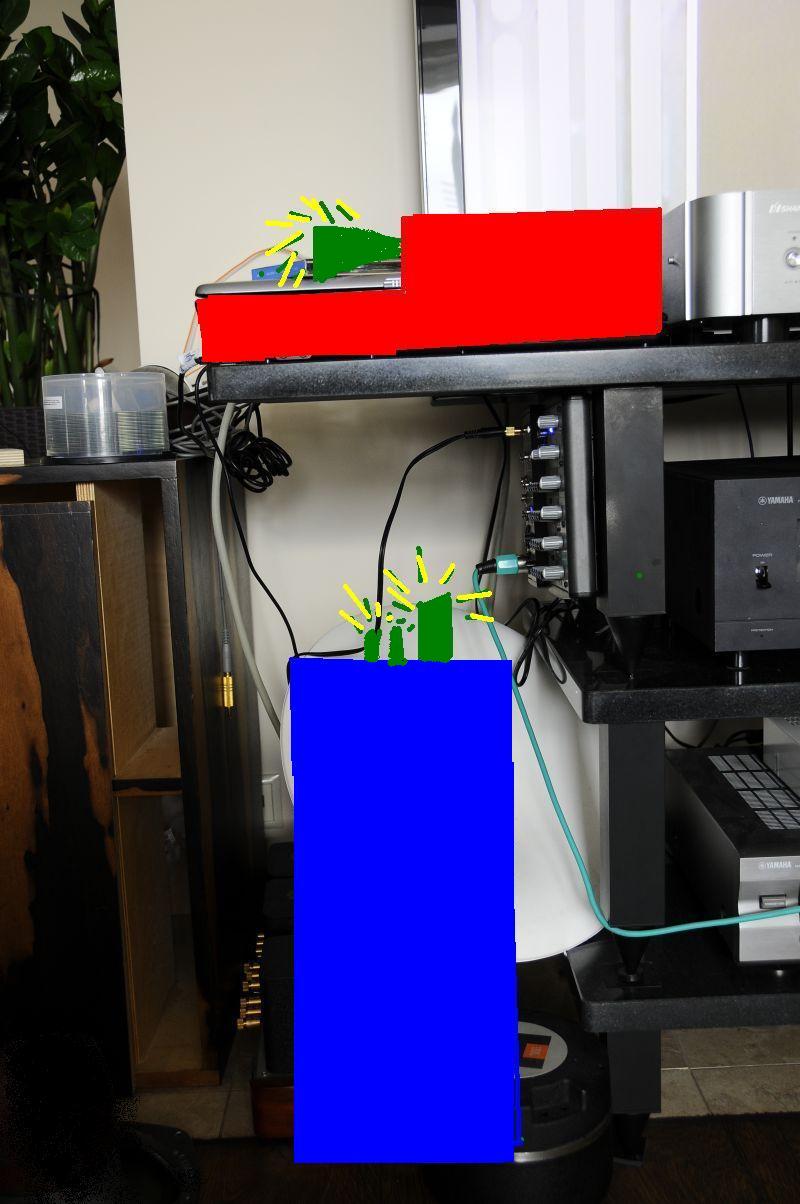
If option one then it could look something like this:amp proiect.jpg

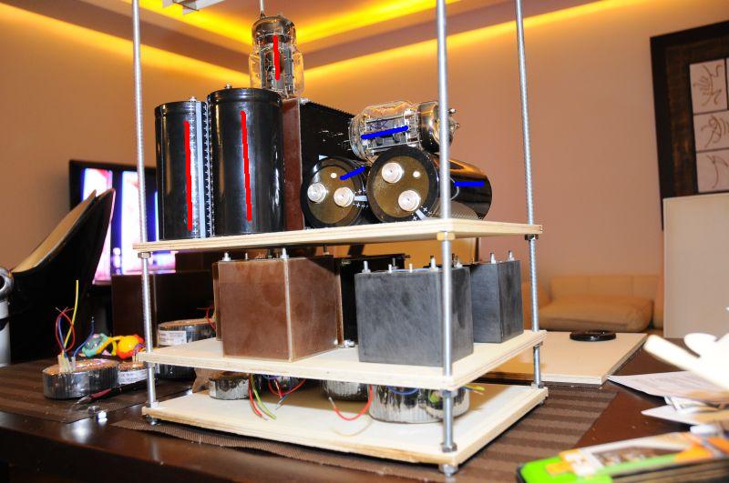
Toroids sit on first floor. it could by vertical or horizontal position of transformers.

On second floor there are the chokes, next floor is OPT and big caps. Position of caps and lamps can by red or blue(to shorten way to chokes if it is nessesary).

What do You thing?


Best 

Dominik


03-20-2011 Post does not mapped to Knowledge Tree
N-set
Gdansk, Poland
Posts 609
Joined on 01-07-2006

Post #: 58
Post ID: 15811
Reply to: 15809
Alu +Cu sandwich
fiogf49gjkf0d
is something I've always wanted to try.
If I get correctly, alu must be thick to be +/- efficient
in shielding 60Hz magnetic fields. 10mm or so.

http://www.chomerics.com/products/do...ory_of_emi.pdf

but the internal dumping, the ease of machinning and the looks of
the brushed thick alu!!


Cheers,
Jarek
STACORE
04-19-2011 Post does not mapped to Knowledge Tree
Tax


Sydney, Australia
Posts 17
Joined on 04-11-2011

Post #: 59
Post ID: 16107
Reply to: 6480
Melquiades Schematic Version 4.4 ...where is R7 and R8?
fiogf49gjkf0d
Tax wrote:
"Sorry to ask, but where is R7 & R8 on version 4.4 of the attached schematic, is it a deliberate puzzle to test the Moron or a numbering error?"


The CaT wrote:

"It looks like R7 and R8 are not there. They use to be filter resisters for my DSET version and I did  not put them on. I did not bother to rename the rest resistors.  BTW, if you posted the very same question at the forum then others would also learn that R7 and R8 are missing. My objective is that somebody who would have interest in Milq to use the forum old post as knowledge base."


So for any other interested Melq builders; Please note that the lack of R7 & R8 resistors in the schematic version 4.4 is due to a numbering error. So continue with the numbering for the rest of the resistors.
04-26-2013 Post does not mapped to Knowledge Tree
DA
Posts 12
Joined on 04-10-2012

Post #: 60
Post ID: 19285
Reply to: 16107
Melquiades resistor question
fiogf49gjkf0d
Finalizing parts ordering for full range Melquiades and I have one thing with is unclear to me,  the plate to grid resistor on the 6E5PIs   R23  50R is this correct ?
There is another R23 in the driver power supply .
http://www.goodsoundclub.com/PDF/Melquiades_SET.pdf
RegardsDaniel
04-26-2013 Post does not mapped to Knowledge Tree
Romy the Cat


Boston, MA
Posts 10,049
Joined on 05-28-2004

Post #: 61
Post ID: 19286
Reply to: 19285
Kind of irelevent.
fiogf49gjkf0d
Yes, Daniel, this resistor is somewhere between 30R and 100R, the value is not truly important. The purpose of the resistor is to slightly decouple the potentials of plate to grid, it cares no current and you might use 1/8W resistor or even less. BTW, you mentioned that you use 6E5PI tubes – DO NOT do it. The 6E5PI is not the same tube as 6E5P. That pulse operating tube slightly smaller glass and has very much not usable sound. The 6E5PI tune shall be trashed.

Rgs, Romy


"I wish I could score everything for horns." - Richard Wagner. "Our writing equipment takes part in the forming of our thoughts." - Friedrich Nietzsche
04-27-2013 Post does not mapped to Knowledge Tree
DA
Posts 12
Joined on 04-10-2012

Post #: 62
Post ID: 19289
Reply to: 19286
No 6E5PI
fiogf49gjkf0d
Yes I have 6e5p . The 6e5pi was a typo,I have read your comments about this tube.Btw what kind of fuse (240v) is needed for the amp ?
RegardsDaniel
04-27-2013 Post does not mapped to Knowledge Tree
Romy the Cat


Boston, MA
Posts 10,049
Joined on 05-28-2004

Post #: 63
Post ID: 19290
Reply to: 19289
A fuse.
fiogf49gjkf0d
Hm, that is a good question. I honestly do not remember. The 6ch Super Melquiades has 7A fuse but I have no memory about the fuse I used in single channels amp. During the assembly I used the lamp fuse – that is given but in the final version I just do nor remember. I do think that you will figure out, start from 3A and go ups if it feels too little. Make sure that you use slow blow fuses – this is very important for this design. The amp has input choked and then the current rushes in for the first time you will have a huge current draw. The slow-blow fuse will be holding it.

I still have a pair of full range, single channels Melquiades  and I think I need to plug them in into a watt meter and to wee what current they drown normally. It is possible to calculate it but easy to measure. The amps in the basement and they are very heavy. If you truly need I can do it but I do not think that it shall be so critical for you at this moment. As you make the map, measure the current and use a fuse of 1.5-2.0 times more. I would anticipate that during a normal operation it shall consume around 150-170W that would make it 1.4A, so the 2.5A-3A fuse might do. I however do not remember the actual numbers.


"I wish I could score everything for horns." - Richard Wagner. "Our writing equipment takes part in the forming of our thoughts." - Friedrich Nietzsche
05-21-2013 Post does not mapped to Knowledge Tree
DA
Posts 12
Joined on 04-10-2012

Post #: 64
Post ID: 19370
Reply to: 19290
12v-5v service power supply
fiogf49gjkf0d
As all the parts for the full range Melquiades are making their way to meet me,I'm faced with the need for a 12v-5v service power supply (fan , hour meter, LEDs ).

How to approach the issue ?

1.buy regulated switched (and cheap) power supply and be done with it.
2.build a non regulated CRC power supply with 12v and 5v taps.

If option 1 is Ok in terms of sound that would make things easy.But if not then I would need some help in design (I have no real knowledge in electronics ).

Regards Daniel
05-22-2013 Post does not mapped to Knowledge Tree
decoud
United Kingdom
Posts 247
Joined on 03-01-2008

Post #: 65
Post ID: 19371
Reply to: 19370
Minimalism
fiogf49gjkf0d
For what it is worth, I use this for LEDs:
http://www.vellemanprojects.eu/products/view/?country=be&lang=en&id=379858
...but I have found no need for a fan or an hour meter, either of which would require something more elaborate. 
05-22-2013 Post does not mapped to Knowledge Tree
Romy the Cat


Boston, MA
Posts 10,049
Joined on 05-28-2004

Post #: 66
Post ID: 19373
Reply to: 19370
Service power supply
fiogf49gjkf0d
DA,

I would not use any switched power supply, not to mention that they do not need to be regulated for LEDs, relays and fans. I do not know if you build a full range Milq or more complicated multi-channel version. If it is a full range Milq with only one 6C33C then you truly do not need any fan. I have build-in fan in my full range Milq but I decided do not use it as it was not needed.

Fans can take surprisingly nigh current but if you have DC need only for LEDs and relays then you need super low power PF and it might be anything. You might take a parallel ran from filament and dump it to separate rectifier and filter. It would be under 1 dollar type PS and it will serve you well. All that you would need to do in future what the amp is running to confirm that it will be no auditable impact to the filaments. I do not think it will be but you never know.

The right way to do it, in my view, would be how I did it in my 6-ch Milquades. I have a separate transformer with separate rectifier and filter that serve only 12VDC that I need for all auxiliary service functionality. The right question would be to ask if my 12V DC auxiliary service power share the common ground with the rest amp. Honesty, I do not remember and I do not know as now what would be the right answer. Theoretically the service power might be completely floated as none of the service element has references to gourd. From another perspective anything floated is king of non-kosher and you might try to bias that service power relative to the common ground but running a resistor between minus of service power supply and common ground. I do not think that you will see any snick difference but you might see some noise differences, in particularly if you run service power wires in the amplifier negligently,

Rgs,
The Cat


"I wish I could score everything for horns." - Richard Wagner. "Our writing equipment takes part in the forming of our thoughts." - Friedrich Nietzsche
05-22-2013 Post does not mapped to Knowledge Tree
DA
Posts 12
Joined on 04-10-2012

Post #: 67
Post ID: 19374
Reply to: 19373
The right service power supply
fiogf49gjkf0d
decoud - thanks for the link, nice and minimalist,but as minimalism  is no longer part of this project I need Unfortunately a more complex power supply.


Romy -I'm building a full range amp. But...I need a small foot print so it will be high and relative easy to addMore channels when the time comes.It is three "stories" high, the lower two are the power supply.


A picture of cardboard  first draft.(sorry for the low quality)


A fan (5v) will be put in the amp, I may or not use it for now.
Hour meter (12v)  - I think it's a good idea to have one.


I want to do it once the right way and with that I need help. There are a lot of sites with info but all the ones I could find talkedAbout regulated switched power supply and not for audio .If somebody knows a  simple to understand site that can help ,please please post a link....
05-23-2013 Post does not mapped to Knowledge Tree
Romy the Cat


Boston, MA
Posts 10,049
Joined on 05-28-2004

Post #: 68
Post ID: 19375
Reply to: 19374
Juts put is one extra transformer for now.
fiogf49gjkf0d
DA, from what you say I do not think you need actions to do now.  As I understand the power transformer for the amps most likely has been made. Since you are in design phase and the look forward to have a sever voltage then get 1-2A 12V transformer with single tap at 6.3V. This will be a few inch very small transformers that you can even get in Radio Shake for $10. Place it somewhere in your chassis and forget it. Sometime in future, when you will add to the all the bells and whistles then you will use the voltage of this transformer for whatever you need.


"I wish I could score everything for horns." - Richard Wagner. "Our writing equipment takes part in the forming of our thoughts." - Friedrich Nietzsche
05-24-2013 Post does not mapped to Knowledge Tree
Welborne
Posts 3
Joined on 05-23-2013

Post #: 69
Post ID: 19378
Reply to: 5559
Hello and Fullrange Melquiades schematics question
fiogf49gjkf0d
(sorry, this is supposed to be posted in the questions and answers colume but I must be so stupid to have it posted here and now I don't know how to move it there.)

Hi Romy,

How are you!  This is Welborne, from far across the ocean, Hong Kong. I have known your wonderful blog for long time (because I am a big fan of 6c33 single end and owns a stereo amp with this tube) but only recently I bring myself together to make the fullrange Melquiades.

My loudspeaker system is a Bastanis Mandala Chrystal open baffle system with 100db efficiency. Right now I have a few different amps rollling (D3a-300B DHT, 71a DHT etc) and the one that stands out is a 6c33 single end stereo based on the little pentode 6ac7 triode wired driving 6c33c.

I have not had the chance to hear the Melq, but from my limited exposure to 6c33, there is a spooky realm in the presentation this tube brings about when compared to what other amp does. I am not a tech expert, but I think the unique sound of 6c33 may come from its high transconductance, low internal resistance (meaning very low turns ratio for output transformer), and high current ability (high damping/control over the movement of the speaker unit).

Anyway, charmed by my own experience, I decide to make the Melq. Here are a few questions after I have had a good look at the schematics:

1) There are hexagons on the schematics marked with A, B, C ...M. What are these? Are they testing points or they carry some meaning? I can't find much info about these here.

2) Besides Schottky diodes, I seem to read somewhere that now you find something with better performance, and again I try to find them but got lost in the forum (your blog is huge ^^)

3) I find two R23 in the schematics. I believe this is an error. The one linking the anode and the grid I believe is a grid stopper and can use a 1/4w carbon film I suppose?

4) Regarding C2 and C10, is there an advantage going over the stated 2000uf? and is there a ceiling on the value one should go?

5) Primary impedance of output transformer: I am going for a custom made transformer based on Finemet c core, and I need to decide on the primary impedance for the builder. In my own 6c33 stereo I am using 980 ohm.

6) Here in Hong Kong I could not source Magecraft timer relay as they are all in 120v version (here the mains supply is 230v), so I am just going to use toggle switch to switch them on manually.

7) Meter: Is there a difference using a 300mv and a 300ma meter in terms of calibration?

Thanks for your help in advance.

Welborne

05-24-2013 Post does not mapped to Knowledge Tree
Romy the Cat


Boston, MA
Posts 10,049
Joined on 05-28-2004

Post #: 70
Post ID: 19379
Reply to: 19378
Answers.
fiogf49gjkf0d

 Welborne wrote:
1) There are hexagons on the schematics marked with A, B, C ...M. What are these? Are they testing points or they carry some meaning? I can't find much info about these here.
Yes, the hexagons are test points. Do not worry about them. I have my reasons to make them available.

 Welborne wrote:
2) Besides Schottky diodes, I seem to read somewhere that now you find something with better performance, and again I try to find them but got lost in the forum (your blog is huge ^^)
Yes, in 6-Ch Milq I used new at that time Silicon Carbide Diodes.

http://www.GoodSoundClub.com/TreeItem.aspx?PostID=6116

They are objectively better then any lower noise SS and run up to 1000V. However, I do not insist that they sound better. Also, it was years back, in 2007 and now something ease new might be available. Anyhow, you need to make some kind of test make and try to listen them or talk with somebody who know how they sound.

 Welborne wrote:
3) I find two R23 in the schematics. I believe this is an error. The one linking the anode and the grid I believe is a grid stopper and can use a 1/4w carbon film I suppose?

I did not see two R23 but I remember somebody told me about it before. Anyhow, if it is the case then this is obvious a mistake. The one that links anode and grid of the driver tube is not a grid stopper but a resistor that slightly decuple the potentials of grid and anode. Yes it might be very very low power, 1/8W would be fine but I would not comment about the type of resistor. There are people who like carbons and they might be right. I comment upon something that I tried and likes. The RN-55 from Dale was my chose and I do like those resistors a lot. Again, it was back in 2004 what I made those experiments and the thing might be changed. I have see that large companies that made very good resistors started made them to sound like crap.

 Welborne wrote:
4) Regarding C2 and C10, is there an advantage going over the stated 2000uf? and is there a ceiling on the value one should go?

Well, I feel the 2000uf is a minimum to decuple the PS from the tubes. In case of C10 that run might higher current it might be much higher. In my 6Ch version I went for36.000uF or something like that, I do not remember already. Yes, there are many advantages why the higher value of the last cap is better but they all purely intellectual. I doubt that blindly I will be able to say if Milq’s power tube is driven by PS with 2000uF or 3000uF. I think however that I will be able to say if it will be 470uF in there…

 Welborne wrote:
5) Primary impedance of output transformer: I am going for a custom made transformer based on Finemet c core, and I need to decide on the primary impedance for the builder. In my own 6c33 stereo I am using 980 ohm.
  Hm…. To load 6C33C with 980 ohm is somewhere near where I fill it has to be, at least with the acoustic systems that I tried. Some people swear by 600R but it too much load to 6C33C, they get more power but it did not work for me. Without knowing personally your speakers and a few other parameters it is very hard to guess how you will need to load your 6C33C. In initial stage I used the OPT with re-mapable coils that let me to play with loading variances. Perhaps you might try something like this.

 Welborne wrote:
6) Here in Hong Kong I could not source Magecraft timer relay as they are all in 120v version (here the mains supply is 230v), so I am just going to use toggle switch to switch them on manually.
You can use any other timer relay that you mike and that sound good to you or you can build or buy a very simple SS timer relay.  I think to use manual delay is kind of difficult. However, you can always add it later if you like the sound of the amp and decide to use it.

 Welborne wrote:
7) Meter: Is there a difference using a 300mv and a 300ma meter in terms of calibration?

Nope, you can use voltmeter or ampermeter. There is no difference, and from a good company they are well calibrated. I prefer to use voltmeter as I would like to make sure that the voltage measuring resistor is the resistor of my chose and that signal current doe not flow over the ampermeter wires.

The Cat


"I wish I could score everything for horns." - Richard Wagner. "Our writing equipment takes part in the forming of our thoughts." - Friedrich Nietzsche
06-05-2013 Post does not mapped to Knowledge Tree
DA
Posts 12
Joined on 04-10-2012

Post #: 71
Post ID: 19439
Reply to: 19379
Practical advise for full range Milq
fiogf49gjkf0d
Hi

I'm now at a stage of building the chassis for full range Milq.It will be a two chassis,one power supply and one signal,very similar to Romys super Milq layout.The two will be connected by two separate cables AC and DC.

A few questions please

1.How and where to make ground connection to the chassis (signal and power supply and between them)

2.What are the test jacks near the 6c33c for (bais..)? In the photos there seems to be a resistor connected to one test jackand ground to the other but it is hard to see clearly.

3.How to deal with the difference in gain of 6c33c.or maybe it is not an issue.

Regards
Daniel
06-05-2013 Post does not mapped to Knowledge Tree
Romy the Cat


Boston, MA
Posts 10,049
Joined on 05-28-2004

Post #: 72
Post ID: 19440
Reply to: 19439
Answers
fiogf49gjkf0d
 DA wrote:
1.How and where to make ground connection to the chassis (signal and power supply and between them)

2.What are the test jacks near the 6c33c for (bais..)? In the photos there seems to be a resistor connected to one test jackand ground to the other but it is hard to see clearly.

3.How to deal with the difference in gain of 6c33c.or maybe it is not an issue.

 
Daniel, here what I did. Do not consider it as something that need to be imitated but that was decision and I have my reasoning behind them. I do not insist that I am right however.

1)  The ground connector to chassis on PS side is at rectifier point. I have all rectifiers sitting pretty much of the same very thick copper wire and that wife is grounded right there. The ground connector to chassis on amp side is right at the entry of RCA jack.  The cables that run between the chassis I think have 4-5 wires for ground but I do not remember if both cables have ground. The DC cable certainly does but I am not sure that filament cables do. I think filament cable has ground only from one side but I do not remember now. I think if they are identical length then you can ground both sides and then, after you test for loops you will be able to lift one if you find it necessary.

2)  Sorry, I do not know what you are asking. What test jacks near the 6c33c? There is nothing on schematics.

3)  The difference in gain of 6c33c is serially might be a problem and I did told about it many times. The gain might be not only as they new but they might age with different speed and gain of the identical tubes might (or might not) slightly drift and the go older. Generally it is not so bad but you will be able to see two new tubes with 1-2 dB gain difference. Some you will see some freak tubes with 3-4 dB of gain different but that is rare. It is very easy to much the tubes by gain. You might use the amp itself to do so as this is a very good tube tester. Burn in the tube that you want to use and then set then to run in the amp. Drive the identical signals to the both amps (I use a generator in my tuner – very convenient) and measure the outputs – as simple as this. You can use the acoustic dB miter but this is not accurate, particularly if you use horns. So, measus the voltage on the speaker line. I have a few Dorrough Loudness Meters w/Percent Modulation and they are after calibration is very accurate and very convent. I use it all time to run them across the channels of my 6Ch amp.


"I wish I could score everything for horns." - Richard Wagner. "Our writing equipment takes part in the forming of our thoughts." - Friedrich Nietzsche
06-05-2013 Post does not mapped to Knowledge Tree
DA
Posts 12
Joined on 04-10-2012

Post #: 73
Post ID: 19441
Reply to: 19440
Test jacks
fiogf49gjkf0d
Thank you for answers .


Yes you are right there is nothing about test jacks (I do hope its the right name ) in the schematics. Sorry for not being clear. 
On the thread "Building Melquiades :chronicle of full range" page 1   last post. (post # 20)

http://www.goodsoundclub.com/Forums/ShowPost.aspx?PostID=2502
In the photo your voltmeter is pluged to Melquiades test jacks right behind the 6c33c. What's it's purpose ?
08-19-2013 Post does not mapped to Knowledge Tree
DA
Posts 12
Joined on 04-10-2012

Post #: 74
Post ID: 19943
Reply to: 19441
Melquiades debugging
fiogf49gjkf0d
Well two power supply's ready and one full range amp hooked up.Nothing blew up so that's good!

1) output stage 200mA /187V


2) driver stage 205v (test point A) and -4.3v bais


3)setting 0.000v on input is ok but not stable,some DC drift


4) bais lines are low at around 175v (point L ) and 146v - 147v ( point C and D ).    The power transformer for bais line puts out only 420 v for some reason and not 440v.    at this setting gas tubes draw only 5.5 mA current .


5) Filament voltage is also low at 5.9v . Transformer rated for 6.3 v / 10 A .driver and output connected in parallel    ( 6C33C in parallel heater connection )

Any ideas are well come especially with bais lines...I need at least 20v more....

08-19-2013 Post does not mapped to Knowledge Tree
DA
Posts 12
Joined on 04-10-2012

Post #: 75
Post ID: 19944
Reply to: 19943
Melquiades debugging.
fiogf49gjkf0d
Image in post above is power supply.
And amp in this image.
Page 3 of 4 (97 items) Select Pages:  « 1 2 3 4 »
   Target    Threads for related reading   Most recent post in related threads   Forum  Replies   Views   Started 
  »  New  Full range Melquiades implementation..  Solved...  Melquiades Amplifier  Forum     81  522886  02-23-2011
  »  New  Melquiades For Dummies™ - step by step...  Amp still open...  Melquiades Amplifier  Forum     28  202354  08-29-2007
  »  New  Building Melquiades: Chronicle of full-range..  VR2 issue leading to jump in current on 6C33 tube...  Melquiades Amplifier  Forum     44  411965  06-09-2006
Home Page  |  Last 24Hours  | Search  |  SiteMap  | Questions or Problems | Copyright Note
The content of all messages within the Forums Copyright © by authors of the posts