| Search | Login/Register
   Home » Horn-Loaded Speakers» Deep End DIY - Australian take one Macondo. (88 posts, 5 pages)
  Print Thread | 1st Post |  
Page 2 of 4 (88 items) Select Pages:  « 1 2 3 4 »
   Target    Threads for related reading   Most recent post in related threads   Forum  Replies   Views   Started 
  »  New  Macondo Frame modification...  Parquet...  Horn-Loaded Speakers Forum     46  464345  12-22-2006
  »  New  Macondo's Axioms: Horn-loaded acoustic systems..  A link to another thread....  Horn-Loaded Speakers Forum     120  681405  07-29-2007
  »  New  Designing and building a 5 channel horn loaded (looking..  The "old" servo......  Horn-Loaded Speakers Forum     73  344391  06-20-2015
  »  New  Another time aligned 5-way horn project..  Thread moved...  Horn-Loaded Speakers Forum     189  881905  08-12-2015
  »  New  5-ways from Speedysteve7..  Hehe - no invite for you...  Horn-Loaded Speakers Forum     23  206478  05-20-2011
  »  New  Jessie Dazzle Project..  Will this better to be auditable?...  Horn-Loaded Speakers Forum     172  1564655  08-03-2007
07-04-2017 Post does not mapped to Knowledge Tree
anthony
Posts 338
Joined on 08-18-2014

Post #: 26
Post ID: 23280
Reply to: 23278
Earthquakes
 Romy the Cat wrote:
Jorge, your comment about the physical instability of the pipe stack is well taken. I think if it is gone from metal then it is possible to make it steady. In the way how Antony want to do the pipe feet I think it might be possible to run guy wire to the top of the pipes hip and to anchor them this way. I am sure the people who are good with industrial design in metal can come up with some solution, it was never my objective to think about it deeper. For sure the design need to be safe and to be more or less portable. It is not the last factor is that it has to be earthquake proved. It sounds ridicules but you do not want to have a minor earthquake and to find your speakers flying to the floor and crash your amps and tonearms. 
 

In my 43 years of life living only in this part of the world I have never felt the ground shake apart from when a neighbour was geligniting tree stumps out of the ground when I was a kid.  That looked so much fun but I was never allowed to join in!

But I do take your point Romy, and to be honest, based on what my experiments have yielded thus far and where I expect the cannon stacks to be placed in the room in the event of an earquake I think they would tilt into the wall and probably crush some gyprock, but I doubt they would bend or topple.

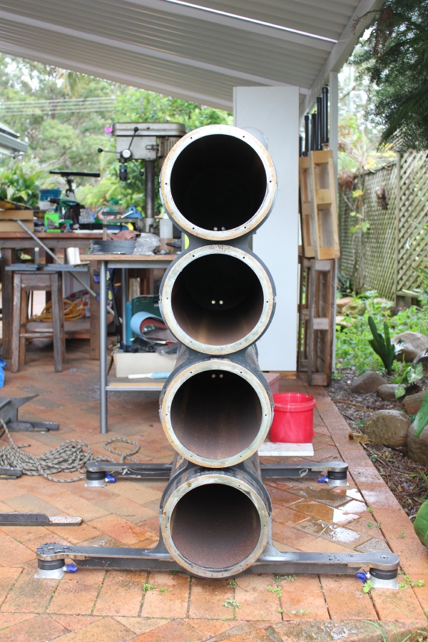
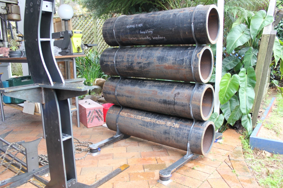
Below are a couple of images from where I have loosely stacked some cannons to try to gauge if the stack was going to be rigid enough...
Cannon Mockup 1.jpg


At 4 cannons high and with only two sets of braces (each without their gaskets) this cannon stack was rock solid.  The braces are 10mm x 10mm steel with M6 double ended screws to bind them together.  Of course as I go higher the situation may change, but I can stop at 6 or 7 or 8 with this design if I have to.
Cannon Mockup 2.jpg


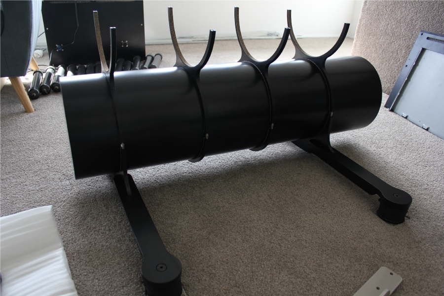
After powdercoating I have experimented with the amount of ringing in the pipes and what level of damping I require.  Below you see one tube with four sets of bracing applied, this time with the 2mm cork gaskets installed.  The braces work as a 'pre-tensioning' device in that they apply considerable pressure to the tube which further increases the rigidity of the pipe walls.  Adding the third brace really knocked the amplitude out of the excitements and decreased the duration of ringing and the fourth brace further improved the result.  However, there was still some residual energy being released as ringing, quite low in amplitude, but still there.  With four braces applied to the 4.8mm wall steel pipe, I would rate a knuckle wrap as the equivalent of doing the same on a 16mm plate of steel.  I researched damping paints as well as automotive butyl rubber/aluminium CLD sheets and have ordered some of the latter to place inside the pipes to eliminate the last of the stored energy.  Driver excursions as going to be quite small if I can get 6 or 8 tubes in a stack so I actually have high hopes that I can make these steel enclosures very inert for their purpose.

Cannon Ring.jpg


 Romy the Cat wrote:

I never was a huge fun of the pipe design that you and Anthony looks like embrace. There is none contestable topological advantage that the pipes might be aligned in a curve to make a very perfect time alignment. This is given. How practical it is I do not know. I think it need to be aligned one pipe a time, starting from the bottom during the pile assembly… Another point is the sharp rollback from the back wall. The pipe design will have a permanent sharp enclosure mode deriving from the one single reflection surface. The pipe des has it as well but there are many reflection surfaces and the modes are kind of defused. With the pipe I think the reflection mode should be only one and it should be more prominent than with box. Saying all of it and understanding that you have good 2 inch foam in the box, or perhaps 4” in the back wall, not to mention that you guys run it all at very LF it is possible as well then my comment about reflection mode are purely theoretical and will be negligible in practice. I never experiment with pipes and do not know what work in them and what is not. 


I will be experimenting with stuffing the pipes.  At this early stage, I want to first see if I can make the enclosure inert and then move on to acoustic testing.


 Romy the Cat wrote:
  
If I were building my system again from scratch and would follow the same topology then I would probably go with stackable individual rectangular boxes with one or with two driver, probably one. The construction of the sealed boxes is VERY not expensive and if you order them in bulk then you get a large discount. But it is me and I do not particularly fide the pipes being more attractive visibly. Also, I am not sure how metal enclosure would work for damping. For sure my opinion shall means very little for those who desisted to use pipes and I am sure that it to make the use the pipes as an objective and took this task seriously then it is possible to make the pipes to work out well…


At this stage I am not wedded to the pipes idea, but am wedded to the idea of a modular bass stack whether that be one or two drivers per box, steel or wood or some other material.
07-04-2017 Post does not mapped to Knowledge Tree
mats
Chicago
Posts 85
Joined on 09-18-2005

Post #: 27
Post ID: 23281
Reply to: 23280
Unwed Mate
Anthony, you crack me up!  
After doing this absolutely amazing work in steel,  
you proclaim that you are "not wedded" to the pipes. 
I love that spirit. Most people would likely at this point
proclaim the unalterable superiority of the design,
and spend years trying to prove it. 
I sincerely look forward to your findings. 
I trust that your detachement will serve us all well. 
Meanwhile, I hope you have time to play some music that 
you love while creating!


Mats


07-05-2017 Post does not mapped to Knowledge Tree
anthony
Posts 338
Joined on 08-18-2014

Post #: 28
Post ID: 23282
Reply to: 23281
Ex-pat?
Mats, your sig says Chicago but you type like an Aussie.  
One thing I have learned in life is that you almost never get good results unless you stay objective.  I just want nice soft bass...

07-05-2017 Post does not mapped to Knowledge Tree
Romy the Cat


Boston, MA
Posts 10,160
Joined on 05-28-2004

Post #: 29
Post ID: 23283
Reply to: 23280
Ok, it looks good now...
Anthony, these last images do give a perspective of the size that made me to feel much better and the pipes are sufficiently large. Purely from visual assessment then are twice larger then what Jorge did and I do welcome it. Frankly, and I have no idea why, when I see just an image from front of the types they look unpleasant to me. However, what I see the side view then they look much more attractive and more holistic. I have no idea why I feel this way. I think it they were my bass modules then I would position them with a slight angle to see the size of the pipes. Is it is funny to hear from a guy who just a few days back was bitching about the angling of horns? Anyhow, you will need to stuff the pipes with foam. It sound a bit contra initiative as you will be losing so important volume of the enclosure but it will be only visual lost. At the LF the foam will be acoustically transparent but it will help to damp the internal pressurizing of the enclosure. It is not about the damping of the walls but rather let the pressure inside to rise gradually, foam will be compressing and smooth the event when the force of the code will be equal to the pressure of the enclosure…


"I wish I could score everything for horns." - Richard Wagner. "Our writing equipment takes part in the forming of our thoughts." - Friedrich Nietzsche
08-28-2017 Post does not mapped to Knowledge Tree
anthony
Posts 338
Joined on 08-18-2014

Post #: 30
Post ID: 23374
Reply to: 23283
Testing of the first Bass Cannon
So, I have finally started testing a single Bass Cannon in my room.

First, I had to get the rigidity as high as possible and then damp the steel ringing as much as feasible.  I used butyl rubber/aluminium automotive deadener on the inside of the tube which really worked well and then on the 10mm thick backplate and frontplate (that the driver screws into) I used the same vicoelastic polymer and 2mm aluminium CLD arrangement that I have been using to great success in the DSET power supplies and amplifiers.  I did some hard knuckle rap tests and measured on my phone the amount of time to stop ringing and I have got it down to about the same as a double brick wall.  There is a local speaker manufacturer that makes my standmounts that puts a lot of effort into low energy storage cabinets and my steel Cannon tubes are damped quicker than those and at a lower frequency.  So rigidity and damping is good for these Cannons...I am very happy.

So I screwed in a driver and was concerned by the sound scratching and tapping the woofer made...it was horrible and there was obviously some energy storage or something similar happening.  I listened to the radio and female voices sounded particularly horrible (yes I know they are being reproduced by a 10" woofer) although the effect was a little more veiled by music.  I figured that a feedback loop was happening between the driver and the flat backplate of the cannon which contributed to the impression of energy storage and ridiculously long decays after the music stopped.  So I cut some leftover fibreglass insulation into the circles matching the inside diameter of the Cannons and stuffed it in...instantly better...good in fact...and I was greatly relieved.

So next item was to do some impedance testing with various amount of fibreglass sheets in the Cannon.  First up with no stuffing:

BC 0 Sheets.jpg


Look at that, the ringing is clearly visible at about 180Hz along with harmonics!  So I added one sheet at a time so that I could identify when the ringing was damped and the effect on Fs and the peak of resonant impedance.  Without boring you with every test, the backplate ringing was damped out with a couple of sheets of fibreglass and another couple further lowered the resonant impedance while adding the fifth started to increase the resonant frequency.  At this stage I think that 4 sheets looks about ideal because it gets the maximum reduction in resonant impedance whilst barely raising the resonant frequency.  Below is a graph of all 0/1/2/3/4/5/10 sheets of fibreglass stuffing in a single Cannon:


BC 10 Sheets.jpg


Using a low output impedance SS amp meant that the frequency response was barely affected by the various amounts of stuffing:

Frequency Response various stuffing 29082017.jpg


It all looks as expected from an SPL point of view.  If I parallel 8 Cannons with 4 sheets of fibreglass stuffing the DSET Bass OPT will see a range of 0.8R - 4R, which is pretty good I think considering it is wound to drive 1R and I am yet to add resistance for speaker cable of which there will be a lot for this channel.  The Cannons are tuned to 47Hz which is higher than I had wished, but adding stuffing has done nothing to reduce Fs but adding more and more does eventually raise it.  I don't know if different stuffing materials would be able to help lower Fs, but it looks like I am stuck at 47Hz
For what it is worth I will do some testing with a fullrange Melquiades with the Bass OPT installed to see how a higher output impedance affects the SPL graph.

Below is a single Cannon ready for SPL testing in-room.  I've not been too OCD about setting up to remove the room from the measuring equation, relying on a short gating to get some idea of what the speaker is capable of. 
Its alive.jpg


08-29-2017 Post does not mapped to Knowledge Tree
Romy the Cat


Boston, MA
Posts 10,160
Joined on 05-28-2004

Post #: 31
Post ID: 23375
Reply to: 23374
That will be fun to experiment.
Looks fine, Anthony. I am not sure what resonance frequency tells you. Anyhow, a great advantage of your pipe topology for LF is that you will be able to pile up as many drivers as you need in order to hit the desired reference DB level.  There is a tricky thing in it. After you properly damp your pipes (and I do not know how to do it properly) the LF will be very sensitive to the way how you load the Milq’s output stage. You want to idle the output stage as much as you can, still without losing gain and power. More idle = faster transients, more load = more harmonics and slower decay. Here is what the trick is. You presumably find a configuration of your drivers and loading and you like sound. You feel that you need juts + 3dB and adding 2 drivers will give it to you. However, adding 2 drivers will change the impedance of the entire LF section and will require a new transformer. So, what you might want to do is to your other Lundahl transformers to fine a proper lodging. Lundahl has very flexible remappable primary and secondary and you can choose any configuration you want. You can even put section in opposite polarity to ask as subtraction sections… very very flexible. You can do some crazy shit like connect all of your LF drivers in parallel, that will form some kind of sub 1R array and to wind a transformer against it. So, it will be a pross for you to find a proper loading, until you do it do not waste money for expensive LF OPT. You can make a large LF transformer with multiple taps of course but it might be a bit difficult as it will be very little wire in the transformer and you might not have the best core filling with each tap. Lundahl  from this perspective is superb – each section in there is perfectly symmetrical and cover all bobbin.


"I wish I could score everything for horns." - Richard Wagner. "Our writing equipment takes part in the forming of our thoughts." - Friedrich Nietzsche
08-30-2017 Post does not mapped to Knowledge Tree
anthony
Posts 338
Joined on 08-18-2014

Post #: 32
Post ID: 23376
Reply to: 23375
Free first order crossover
I realised this morning that I have done a "not-so-standard" thing in using leftover fibreglass batts for stuffing the tubes.  The batts that I have on hand are high density batts, not the low density type of fibreglass that is usually used for stuffing speakers and it is having an interesting effect.  Looking at the spec sheet of these particular batts they start absorbing at about 100Hz and really get efficient at about 250Hz and they are having effectively acting as a low pass filter for the channel.  Completely accidental of course.

Think of if this way.  The backwave from the driver is goes back into the tube and because it is a subwoofer the low frequencies push straight through the fibreglass and some of them are reflected back to the driver and some of them pass through the walls of the tube and into the room...there is no way to stop this and it is what it is, but the more rigid the tube is the less sound that will pass through it.  Because the rear of the Cannons will be placed against a wall the sound that passes through the tube wall and the sound that wraps around the baffle (or no baffle in this case) is reflected off the back wall with a 5.8ms delay or phase shift.  However, the high density fibreglass inside the tube starts attenuating the backwave at about 100Hz and I have reason to believe that almost all of the 200Hz+ backwave is absorbed (the resonance of the pipes is about 190Hz and this is completely removed).  So we have no attentuation of the backwave in the tube at 20Hz, a bit starting at 100Hz and full-on attenuation at 200Hz...that is a low pass filter with the knee set at about 100Hz which is just perfect for this application because this is approximately where the line level low pass filter will be set.

As I mentioned earlier I just used the fibreglass that I had on hand, but it does a good job of removing a lot of out of phase energy above 100Hz which I think is a good thing, while not affecting lower frequencies.  So I think that I have just found an unintended benefit of the tube or Cannon topology.
08-31-2017 Post does not mapped to Knowledge Tree
Romy the Cat


Boston, MA
Posts 10,160
Joined on 05-28-2004

Post #: 33
Post ID: 23377
Reply to: 23376
Hmmm… I can’t comment on this.
Hmmm… I can’t comment on this. I never played with pipe and I do not know what works and what does not in there. I think to worry about high pass filtration via the foam inside the pipes is not what I would care. The foam in there to virtually evened the size of the enclosure and therefore to drive resonance frequency down. The resonance frequency itself does not say much and what does, in my view, is how and what the sound drivers produce. I know the drivers very well and I always appreciate in them softness with which the can play bass. It is a bit contra-intuitive and everyone is looking for had-ass bass and a lot of punch. It is very easy to get it from this drivers, just drive it with some kind of SS crap. To get the driver to play fast attack with gentle release is VERY hard. In my view those driver is they are properly loaded can produce very good result in the fast-attack -gentle-release department.  The amplification just need to be right and the loading need to be very sensible. If I were you I would male at this point the pipe hollow and empty (juts a smalls layer perhaps) and would think about the specifics of  damping by filler after the LF amp will be in place.


"I wish I could score everything for horns." - Richard Wagner. "Our writing equipment takes part in the forming of our thoughts." - Friedrich Nietzsche
08-31-2017 Post does not mapped to Knowledge Tree
martinshorn
Germany
Posts 114
Joined on 04-14-2017

Post #: 34
Post ID: 23378
Reply to: 23377
TSP related
Hi Anthony. No miracles. Round shapes happen to be far more rigid than flat. That will also increase the pressure on the flat opposite plate, which has to be of quadruple stability. You can easily eliminate this by the so called impulse compensation of installing one more driver on the opposite of the pipe. Alternatively a long rigid metal bar tension connecting plate and magnet.  
Anyhow this is less a wall instability interference, but rather a reflection. At 180 cycles lambda/2 equals about 3 feet. Stuffing eliminates that pretty good. Long layers in small closed cabins let the standing wave decrease way more than the free field absorband spec assume. Especially that absorbency of 0.3 are sufficient already. 
Stuffing influences TSP easily predictable when u check via TSP calculator playing with your given cabine size multiplied by 1.1 or 1.2 up to 1.3 for heavy stuffing (proven to be most common values). How much it lowers the fs depends on the VAS, meaning indirectly the suspension stiffness. If you got low VAS, like 50 or less, it wont influence much anyway. But it gets you Qts down which may look like a hipass, but actually just lowers the knee of the filter while increases xcursion on the subsonics. Still a highpass second order, just lower Q. 
A little side note from my side: i happened to find the Sound more boring and tired when stuffing, though the measures are better. Cant explain why. Id rather try to avoid stuffing but stay away from the resonance with my passband. Alternatively use little stuffing only which decreases the ringing already dramatically (ideally in the middle of the pipe just a piece of foam, most efficient in the middle!). 
Cheers, Josh 
09-02-2017 Post does not mapped to Knowledge Tree
anthony
Posts 338
Joined on 08-18-2014

Post #: 35
Post ID: 23380
Reply to: 23378
Improved stuffing
Thanks Josh,

I tried the "stuffing in the middle of the pipe" and with 2 sheets in the middle managed to get very similar results to 4 sheets placed at the far end of the tube, but with a steeper SPL curve.  I then tried lower density stuffing and managed to remove most of the ragged SPL response above 150Hz (it also had a tidier impedance response in that region) so I am now on the hunt for lower density stuffing to see if that is going to improve things further.  

The lower density polyester wall batts also managed to reduce Fs as more were added, and it looks like I may be able to keep Fs at 45Hz or thereabouts with a drastically lowered resonant peak which will help things when I start testing with a Melquiades LF amplifier and its higher output impedance.  I have a room node that may be easier to manage if I can get that Fs lower in frequency, about 40Hz would be optimal, but I don't like my chances of getting there with the use of even less dense stuffing.  We will see.

Cheers,

Anthony
09-02-2017 Post does not mapped to Knowledge Tree
martinshorn
Germany
Posts 114
Joined on 04-14-2017

Post #: 36
Post ID: 23381
Reply to: 23380
Such trials are fun
hi anthony, have fun with that, results are worth it. 
Your findings don't need to match mine but i share my favorite briefly SmileI found explanation from an famous german engineer. Hes calculating an Rms thiele small to indicate mechanical friction losses in drivers. He found that some sound tired and boring when having hi loss.Its got common ground with stuffing in my opinion and explained my impression. So if i had your tubes, id stuff a hi density foam disk into the middle of the pipe. Same diameter, maybe 10-20cm max depth. Hi density breaking fragile foam, like 10.000-15.000 density. Which is highly effective, eg sold by BASF as "melamine foam". That could be the minimum damping just to kill the ringing to a neglectable level. Rest of the pipe id keep blank. Also install the foam disk rigid in place not to move under vibration. Just my 2 cents. Was experimenting with a Lowther driver that got very "transparent " membrane and so very sensitive to cases and stuffing. Thick n heavy woofer may react less sensitive. 
09-03-2017 Post does not mapped to Knowledge Tree
anthony
Posts 338
Joined on 08-18-2014

Post #: 37
Post ID: 23382
Reply to: 23381
The melamine
As it so happens I have some melamine here and I cut up 5 x 1" thick discs and pushed them into the middle of the tube (I also trialled 1 disc and 4 discs) and while they removed the resonance they did the same thing as the high density fibreglass batts in that they created impedance wiggles from about 100Hz+.  These impedance wiggles transferred into SPL wiggles and I doubt that they will be a good result.  Also, the closed cell and hardness of the melamine seemed less effective than the other stuffings at absorbing frequencies over 200Hz, but I am glad that I tried it.

Based on my measurements thus far, GreenStuf R1.5 Wall Batts (a low density polyester fibre) placed at the midpoint of the tube seem to do the best job at providing a smooth impedance and frequency response in the 100Hz+ region whilst also eliminating the tube resonance, so that is the direction in which I intend to pursue.

Thanks for your help Josh.
09-03-2017 Post does not mapped to Knowledge Tree
martinshorn
Germany
Posts 114
Joined on 04-14-2017

Post #: 38
Post ID: 23383
Reply to: 23382
Don't forget the ears
hi Anthony. Don't forget to make a brief listen with the stuffings. I predict u might be surprised. Especially with focus on "live sound", soul, tapping feet, joy etc... crunchy beat vs fat slow base Smile
10-01-2017 Post does not mapped to Knowledge Tree
anthony
Posts 338
Joined on 08-18-2014

Post #: 39
Post ID: 23432
Reply to: 23383
The half-stack
I have finally put together a half-stack of my Bass Cannons concept.

Half Stack Side.jpg


Half Stack Front.jpg


The four Cannons wired in parallel and stuffed according to my previous trials on a single tube end up with Fs=41.7Hz and an impedance response as shown below...


Half Stack.jpg


...which means that when 8 Cannons are in the stack the impedance will vary from 0.85R to 2.9R at resonance which nicely suits the Bass OPT that I have here.  To test the half-stack I soldered in the Bass OPT to the prototype Melquiades circuits and took some measurements and did some listening.  The SPL response is quite linear which is good and the cabinets behaved themselves when I played sines between 10Hz and 100Hz...not many vibrations and steel ringing very well under control.  In comparison to the small 2 way standmounts I have here the sines were easy and uncompressed and undistorted to listen to, a really huge difference in tone and yes, I was pushing the two way harder than it would like, but the volumes were similar.

Although not really fair, that little test has driven home to me just what these Cannons can bring to my audio.  Only fools listen to sine waves but in this instance it was very instructive and helped me out in a "you've made all this effort but does it actually do what id needs to do?" kind of way.  Yes, they work, and they are a quantum leap forward from those little standmounts.

Here is the prototype Melquiades and the big bass OPT pushing sub 2R into the half-stack...

Ah valves.jpg 


So, at this stage it looks like the Bass Cannons project is a "go" to finish.  They actually look pretty good in the room, and you can see that I have begun by time aligning them for a 2.35m listening distance. 
10-02-2017 Post does not mapped to Knowledge Tree
Romy the Cat


Boston, MA
Posts 10,160
Joined on 05-28-2004

Post #: 40
Post ID: 23434
Reply to: 23383
Looks VERY good.
I need to give it to you and I need to retract my comments about your bass pipes. I did find them to be ugly in your prototype drowning but assembled I find them look very present, in fact quite wonderful.  Connection al, of then in parallel is good and bad. The good part is that drivers will not work over each other, the bad part is that you need a very precise match of Milq output transformer to drive them.  It is a .2-.3 of transformer ratio in this or that direction and you will be losing dumpling. I hope you have a lot of tap in your transformer. In some way it is convenient to connect them in combination on order to have a conventional impedance and then you can tray many non-custom transformers.  
 
I am glad you made the Melquiades prototype. Drive your bass section with 0dB digital (max that your DAC outits) and see the voltages you have at grid of first tube and how close the output tube approached to class A2. With 6C33C you do not want to enter A2, I would advise to stay under 85% of A1. Load your bass array, drive full power and get sympatric clipping on your Milq output stage. Then get with your RTA sweep and see if your 4 driver can load the room. If you have no enough gain or power then add another pair of your bass tubes. You understand that the more you put the tubes in duty then easier it will be for everything. Still, you might try it even now. I did not know your room and if you have let say -12dB at 40Hz then the given amp or LF section might not be for your room. There are many options if it is the case, like switching from 6C33C to 211 or GM70 but I thing if your room is not over 10000 sq feet then you should be fine with a reasonable amount of bass drivers. My current room is about 550 sq feet and I get a full 20hz from 6 drivers…


"I wish I could score everything for horns." - Richard Wagner. "Our writing equipment takes part in the forming of our thoughts." - Friedrich Nietzsche
10-02-2017 Post does not mapped to Knowledge Tree
anthony
Posts 338
Joined on 08-18-2014

Post #: 41
Post ID: 23435
Reply to: 23434
I am happy with them
Thanks Romy.  To be honest they look better in the flesh than I had thought they would so I am very happy with them.  I think I'll make the steel order today so I can finish them at my leisure.

If I end up with 8 drivers a side, which is what I am planning, I have the option to mix serial and parallel wiring to get to the ideal impedance load for the Bass OPT.  It will be very easy to change the wiring on a whim.  

My room is 406 sq feet, so quite a bit smaller than yours and I am sure 8 drivers a side will be plenty to load the room.  My main concern is whether my dac has enough output (about 1.5Vrms I think) to drive the DSET to the required volume.  If it does not then I will have to investigate a gain stage.
10-02-2017 Post does not mapped to Knowledge Tree
Romy the Cat


Boston, MA
Posts 10,160
Joined on 05-28-2004

Post #: 42
Post ID: 23436
Reply to: 23435
The time will show.
 anthony wrote:
Thanks Romy.  To be honest they look better in the flesh than I had thought they would so I am very happy with them.  I think I'll make the steel order today so I can finish them at my leisure.

If I end up with 8 drivers a side, which is what I am planning, I have the option to mix serial and parallel wiring to get to the ideal impedance load for the Bass OPT.  It will be very easy to change the wiring on a whim.  

My room is 406 sq feet, so quite a bit smaller than yours and I am sure 8 drivers a side will be plenty to load the room.  My main concern is whether my dac has enough output (about 1.5Vrms I think) to drive the DSET to the required volume.  If it does not then I will have to investigate a gain stage.
  
Yes, they do look in flesh distinctly different and frankly quite beautiful. Somebody who is looking a commercial venture out it should take notice. With a room of 400 sq feet you should be able to go away with 6 drivers in case you have not completely open floor plan and the room has as least some walls. 8 drivers still will be better, 44 drivers will be even more better… About the DAC. The 1.5Vrms is relatedly high voltage, most of the line level devises have 500mV. No one knows of you have enough gain for your room, it is depending from so many factors. In worse case you can always get a preamp with gain, there are tone of them out there you just need one with VERY low output impedances and preferably a direct coupled. The Milq has 4.5V at the grid of first tube and it is swallow any voltage with no need to inject a feedback to rise the bias and Lamm does for instance. The first stage has ~33dB gain, the second stage 4 time gain if I am not mistaken, so figure out how much you have burned in your output transformer. To calculate gain is not hard to figure out how much gain your room need is much more difficult. With very good recording that has a very low compression you would need MUCH more gain but “thankfully” we do not has a lot of ultra-low compression recordings…


"I wish I could score everything for horns." - Richard Wagner. "Our writing equipment takes part in the forming of our thoughts." - Friedrich Nietzsche
10-02-2017 Post does not mapped to Knowledge Tree
anthony
Posts 338
Joined on 08-18-2014

Post #: 43
Post ID: 23437
Reply to: 23436
Speaker cables
I've been thinking about how I am going to wire these Bass Cannons as well as the horns on the horn stack.  For some time now I have preferred ribbon/foil speaker cables for the relatively low sensitivity speakers I have been using.  The reason I believe is that the particularly low inductance of copper foils "helps" flesh out the bass so nicely, but I am wondering if they are particularly suited to my application with Macondo and in particular the Bass Cannons.

By their nature, foils are low R, high C and very low L.  Two foils 0.05mm apart are able to reduce inductance to vanishingly low levels, but this closeness boosts capacitance.  Each Cannon will need a metre of wire to get to the back of the tube, and then an average of about 75cm to get to the "junction box" (this is where the wires are starred to their individual Cannons in series/parallel or any combination thereof).  That is 14m of speaker wire or 28m of copper foil that would normally be considered internal to the speaker.  From the amplifier to Junction Box would be no more than a 1m run so this is very simple.  With paralleled drivers, another way of thinking about it is that each driver has a 2.75m speaker cable to it once you go 1m from the amp to Junction Box and 1.75m on average from Junction Box to each individual driver.  That is a lot of foil!  More importantly that is a lot of capacitance for the amplifier to see and I don't know if it will be a problem.

Foil cable capacitance is in the order of 1nF per metre.  14m of foil cable = 14nF of capacitance that the Melquiades Bass Channel will see.  Most speaker cables would be around one-third of that capacitance (but 10 times the inductance).  On one hand long speaker cable runs are where you would expect to experience differences in sound due to different speaker cable electrical properties, and this is certainly a lot of speaker cable (14 metres or 46 feet) but is there any way to know if it will be too much capacitance without trial and error? 

The other channels are fine.  The RAALs will have B+ taken to them so no speaker cables are required.  The 3 horns are quite close so I can make foils for them, if that is really required considering the sub 1m lengths required for the Upperbass and MF channels.

All input welcomed.
10-03-2017 Post does not mapped to Knowledge Tree
Romy the Cat


Boston, MA
Posts 10,160
Joined on 05-28-2004

Post #: 44
Post ID: 23439
Reply to: 23437
You will always have a chance to do it in future
Anthony, it might be a reasonable question but I will not put myself in a position to pretend that I know the answer. In my past I spent a LOT of time to deal with cables and I know that any rationalization you apply to it is faulty as the cables sound in the way how they sound. I think the demands in DSET setup is slightly different. For you MF channel you do not need the cable that do “good bass”. There us alternative to this view and I also support it: the cable that do “good bass” frequently does better job with MF channel lower knee. Then there is question what does it mean “better”? Volume, noise, transients, harmonics, masking effects, etc, etc, etc? There are so many things in the entire system that do the same! It takes some really familiarity with you own playback, really deep and thoughtful listening and thinking and really high performance of the entire playback to identify the very minor contribution of individual cable. Warn you that this “contribution” might be non-permanent, so it is a relay mess to deal with. 
 
So, if I were in your shoes I would not worry about it at all. Use any generic “speaker wire” that you might buy for $15 for 100 feet at Amazon, cut them to the length you need and do not worry about the cables. As your playback will be up and you will address any other major problem with sound you will send the kids to college wand will have time to audition cable and to dial in exactly what your individual channels will need, or what you think they need. The exemption would be RAAL, what the cable between transformer and foil in the tweeter mush be super short and must be two foils stack together. Alex should be taking care about it for you as the cable after a transformer with 175 transforming ratio is a very different beast. 
 
One more aspect that you might not consider now. You might like your copper foils now but you looks like are building a very “neat” looking architectural assembly. As you will be done you might not like the look and feel of 12 copper foils running from your amps to your drivers. Moreover, if you decided to run the copper foils across your metal frame you might recognize that the sound of your copper foils will changed when they are “glued” to a metal surface. So, you might go for more manageable black and flexible cable, perhaps something that you might hide in some kind of nice decorative cable housing. You will always have a chance to do it in future….


"I wish I could score everything for horns." - Richard Wagner. "Our writing equipment takes part in the forming of our thoughts." - Friedrich Nietzsche
10-03-2017 Post does not mapped to Knowledge Tree
anthony
Posts 338
Joined on 08-18-2014

Post #: 45
Post ID: 23441
Reply to: 23439
It may not be the right time...
...to obsess about speaker wire.  Thinking about this a little more I realise that my preference for foil cables has always been in relation to speakers with passive crossovers.  DSET is much more simple, the amplifier is driving the transducer directly without any other reactive components in the way so in theory should have a much easier time of it.  

I've just done some calculations for power loss versus cable gauge and I think that with that length of cable that I would be best off with as low a resistance as possible.  It seems to be an absolutely overriding factor.  If my calcs are correct an 18 gauge speaker cable would burn 4dB or 5.5watts and into 1R the 6C33C grid clips at about 9watts...that's half my power gone just by using an undersized cable plus it really destroys the damping factor.  6 gauge wire on the other hand will burn 0.64 watts or about 0.32dB and keeps the damping factor largely intact.  I was missing the forest for the trees!

So super low resistance is my way forward.  There is some Belden 6AWG wire that I have found which might just be the ticket.

EDIT:  It gets even worse...I just realised my numbers above are with a one way  and not return trip from speaker to amplifier.
10-03-2017 Post does not mapped to Knowledge Tree
Romy the Cat


Boston, MA
Posts 10,160
Joined on 05-28-2004

Post #: 46
Post ID: 23442
Reply to: 23441
I do not think so....
 anthony wrote:
I've just done some calculations for power loss versus cable gauge and I think that with that length of cable that I would be best off with as low a resistance as possible.  It seems to be an absolutely overriding factor.  If my calcs are correct an 18 gauge speaker cable would burn 4dB or 5.5watts and into 1R the 6C33C grid clips at about 9watts...that's half my power gone just by using an undersized cable plus it really destroys the damping factor.  6 gauge wire on the other hand will burn 0.64 watts or about 0.32dB and keeps the damping factor largely intact.

I am sorry. I am not familiar with this calculation but I think your number a bit ridicules. You are saying that a speaker cable burn 4dB of a signal? A typical wire of 18ga has around 5R resistance but it is per 1000 feet. If you have 3 feet of cable then the resistance of your cable truly negligible. I never factor in the “cable burn” in whatever I do. Perhaps I was wrong …


"I wish I could score everything for horns." - Richard Wagner. "Our writing equipment takes part in the forming of our thoughts." - Friedrich Nietzsche
10-03-2017 Post does not mapped to Knowledge Tree
anthony
Posts 338
Joined on 08-18-2014

Post #: 47
Post ID: 23443
Reply to: 23442
The loss is related to speaker impedance
I think I am correct, but the problem is directly related to loudspeaker impedance.  I did the first round of calculations by hand and when I got the results I searched the web for a calculator that someone has made so that I did not have to write it into a spreadsheet.  This is the calculator I just found:

http://www.electrovoice.com/cableloss.php?

It more or less agrees with my calculations.

With higher speaker impedances there is no issue with smaller speaker wires, but as load impedance drops a fair amount of amplifier power is lost in the cable and low resistance becomes more important.  So if I have 92 ft (28m) of speaker wire that meets a 1R speaker impedance I basically cannot have too little resistance.  

But...

The bit that is doing my head in at the moment is whether I have modelled it correctly.  I have 1m of speaker cable from the amp to the Junction Box which will see 1R representing the entire stack of Cannons.  From the Junction Box I'll have 1.75m of speaker wire to each individual driver that will see 7R (not 1R as I have modelled earlier) so perhaps the wire gauge does not matter so much here.  You are most likely right and I've created a storm in a teacup!


10-03-2017 Post does not mapped to Knowledge Tree
anthony
Posts 338
Joined on 08-18-2014

Post #: 48
Post ID: 23444
Reply to: 23443
For my own clarity
Just in case I loose the envelope this is written on, below are the SPL losses for a full 8 driver Bass Cannon stack with different gauge speaker wires modelled with 1R amp to speaker and 7R for each driver:

18 awg = 2.16dB loss
16 awg = 1.37dB loss
10 awg = 0.34dB loss
6 awg = 0.12dB loss

I have some nice 18awg wire here but it is too lossy for this application and the foils would be 15.5 awg equivalent so they are of no use either.  10awg looks to be the sweet spot because it is much more available than 6awg wire.
10-04-2017 Post does not mapped to Knowledge Tree
Romy the Cat


Boston, MA
Posts 10,160
Joined on 05-28-2004

Post #: 49
Post ID: 23445
Reply to: 23444
Ok, I got your point.
Hm, ended, I have learned something. I did use fat wired only once where I was running cable to my midbass horn at my old house. In there I had 75 feed and I went with 2Ga welding wire, I cat them off and I still have them. I did not think about it otherwise as I did not have any long cable runs. I still do not think it is should be a big deal with you as your is very close to speaker. Sill, be my guess and do use 10ga wire for internal wiring. 


"I wish I could score everything for horns." - Richard Wagner. "Our writing equipment takes part in the forming of our thoughts." - Friedrich Nietzsche
10-05-2017 Post does not mapped to Knowledge Tree
anthony
Posts 338
Joined on 08-18-2014

Post #: 50
Post ID: 23446
Reply to: 23445
I decided to test the maths...
...so I measured Vac at the Junction Box for a -12dB 120Hz sine.  And I measured a DC-200Hz sweep in REW.

Then I added 8m of 14AWG wire between the amp and the Junction Box and measured the same things.

By adding the 8m of 14awg Vac at the Junction Box dropped 12% and the SPL sweep show a SPL drop between about 1dB and 0.2dB across the spectrum, average if I had to guess was about 0.5dB.

Then I did the maths to determine what the drops should have been:  11.5% and 0.55dB.  That is very close!  I think that I am on the right track and so that I don't burn too much amplifier power I really do need very low resistance cables.
Page 2 of 4 (88 items) Select Pages:  « 1 2 3 4 »
   Target    Threads for related reading   Most recent post in related threads   Forum  Replies   Views   Started 
  »  New  Macondo Frame modification...  Parquet...  Horn-Loaded Speakers Forum     46  464345  12-22-2006
  »  New  Macondo's Axioms: Horn-loaded acoustic systems..  A link to another thread....  Horn-Loaded Speakers Forum     120  681405  07-29-2007
  »  New  Designing and building a 5 channel horn loaded (looking..  The "old" servo......  Horn-Loaded Speakers Forum     73  344391  06-20-2015
  »  New  Another time aligned 5-way horn project..  Thread moved...  Horn-Loaded Speakers Forum     189  881905  08-12-2015
  »  New  5-ways from Speedysteve7..  Hehe - no invite for you...  Horn-Loaded Speakers Forum     23  206478  05-20-2011
  »  New  Jessie Dazzle Project..  Will this better to be auditable?...  Horn-Loaded Speakers Forum     172  1564655  08-03-2007
Home Page  |  Last 24Hours  | Search  |  SiteMap  | Questions or Problems | Copyright Note
The content of all messages within the Forums Copyright © by authors of the posts