| Search | Login/Register
   Home » Melquiades Amplifier » Planning my DSET (187 posts, 10 pages)
  Print Thread | 1st Post |  
Page 7 of 8 (187 items) Select Pages:  « First ... « 4 5 6 7 8 »
01-07-2019 Post does not mapped to Knowledge Tree
N-set
Gdansk, Poland
Posts 609
Joined on 01-07-2006

Post #: 151
Post ID: 25231
Reply to: 25230
EI vs toroids
Congratulations on the build!

 anthony wrote:
  Yours uses all toroids, or mostly so, which are more efficient than the EI that I use.

Why have you chosen EI vs toroids? The latter emit less.

Cheers, Jarek


Cheers,
Jarek
STACORE
01-08-2019 Post does not mapped to Knowledge Tree
anthony
Posts 335
Joined on 08-18-2014

Post #: 152
Post ID: 25232
Reply to: 25231
Its about noise
 N-set wrote:
Congratulations on the build!

 anthony wrote:
  Yours uses all toroids, or mostly so, which are more efficient than the EI that I use.

Why have you chosen EI vs toroids? The latter emit less.

Cheers, Jarek

Hi Jarek,

Yes, toroids can leak less magnetic flux than EI if they are wound such that the entire core is covered, but is flux leakage a problem if you are able to keep the transformers away from sensitive circuits?  Toroids come into their own when you are forced to mount the transformer near the circuits, but otherwise EI have them covered on most fronts.

Toiroids
  • are smaller for the same power rating
  • are more efficient transformers of power than EI
  • if carefully made can have low flux leakage
  • are high bandwidth devices so more noise on the power line is transferred into the circuit
  • have no gap and will hum when there is DC on the mains


EI
  • are larger for the same power rating
  • have a gap and do not hum when you have DC on your mains (unless there is so much that the core becomes saturated)
  • are lower bandwidth devices so act as a low pass filter for mains noise (we really only need to pass 50/60Hz - the rest is unwanted)
  • leak some flux so they should be kept further separated from the sensitive circuits


Personally, I would use EI in just about every situation for audio...unless I had no option but to tuck the transformer in tight to a sensitive circuit.


Cheers,

Anthony
01-08-2019 Post does not mapped to Knowledge Tree
anthony
Posts 335
Joined on 08-18-2014

Post #: 153
Post ID: 25233
Reply to: 25232
The pin 8 question
Hi Romy,

I've been reading the 6e6p-dr datasheet and it seems as though pin 8 (a shield) is recommended to be tied to a lower negative voltage than the tube cathode.  Have you bothered or experimented with this?  This is no problem in the DHT Channel because of the cathode resistor, but in Channel D the cathode pin is connected directly to ground and I don't know how to get a potential lower than ground.
Regards.
Anthony
01-08-2019 Post does not mapped to Knowledge Tree
N-set
Gdansk, Poland
Posts 609
Joined on 01-07-2006

Post #: 154
Post ID: 25234
Reply to: 25232
Cont'ed
Anthony, thank you for the explanations. For some reasons you mention, I use C-cores. Loose coupling (pri and sec on the different legs), controlled gap and low emission. BTW toroids do have some "distributed gap" but it's small and uncontrollable.

Cheers, Jarek


Cheers,
Jarek
STACORE
01-09-2019 Post does not mapped to Knowledge Tree
Romy the Cat


Boston, MA
Posts 10,049
Joined on 05-28-2004

Post #: 155
Post ID: 25235
Reply to: 25233
A good question.
Anthony, I grounded in my amp it in order the shield was not hanging there free. You certainly must NOT leave it disconnected and you do need to tie to something. Generally biasing of these electrostatic fields shields is very murky territory. There is a community of people out there who insist that it makes difference and I have seen even some gizmos that introduce bias to external shields. The shields in 6E6P is much closer to anything, so a positive or negative bias might be effective. I did not experiment with it and I have no way to predict how it might impact sound. Do not take it too far as I can see you running an active feedback loop over the 6E6P shield… :-) 
 
Let me know if you do experiment with it and what you find. I would be looking for noise and sound impact. Do not forget to burn a used tube at least 1Hr before you make any judgments. It might be hard for you as you do not have 6E6P in a full bandwidth channel and to make any concussion within a narrow bandwidth channel you need the whole system to be setup, calibrated and it sound to matured in your own perception.


"I wish I could score everything for horns." - Richard Wagner. "Our writing equipment takes part in the forming of our thoughts." - Friedrich Nietzsche
01-22-2019 Post does not mapped to Knowledge Tree
anthony
Posts 335
Joined on 08-18-2014

Post #: 156
Post ID: 25239
Reply to: 25229
Barbirolli Mahler
 Romy the Cat wrote:

If you like very slow interpretation, like I do, then you might start to listen some Barbirolli Mahler… 


I've found Barbirolli Mahler 6 & 9 by New Philharmonia Orchestra and Berlin Philharmonic respectively.  I'll give the records a spin when they turn up.  Also grabbed Mahler 7, Bernstein NY Philharmonic.
01-22-2019 Post does not mapped to Knowledge Tree
Romy the Cat


Boston, MA
Posts 10,049
Joined on 05-28-2004

Post #: 157
Post ID: 25241
Reply to: 25239
Yep, Barbirolli would do it...
When I was making a sarcastic joke about you begin to enjoy slow interpretations (something that any VERY good playback should do to a system owner) and referred you to the Barbirolli’s Mahler of cause I mean the exquisite  performance of 1967 of Sir Barbirolli with New Philharmonia. The “Allegro” movement is so much out of this would that I hardly believe anybody would listen any other version of Mahler 6 after listening to what Barbirolli did with it. It was told that Rostropovich pull out all his own recordings of Elgar cello concerto and never recorded it again after he heard the Jacqueline du Pre’s  take on the concerto in August 1965, ironically with the same Barbirolli… I have no idea why people keep recording the M6 after Barbirolli 1967. Whatever was possible to be expressed in that music was done by maestro Barbirolli.  


"I wish I could score everything for horns." - Richard Wagner. "Our writing equipment takes part in the forming of our thoughts." - Friedrich Nietzsche
01-31-2019 Post does not mapped to Knowledge Tree
anthony
Posts 335
Joined on 08-18-2014

Post #: 158
Post ID: 25254
Reply to: 25241
First music testing
So, the first DSET is still downstairs on the electronics bench and I am back to work for a while, but not too hard and not for too long (I hope).  I've added all the filters and checked and tested and changed some more things and decided that it was time to see if I could get any music to play.  Several crappy drivers and speakers that I had scrounged for just this purpose were wired up and I pressed the go button to stream some Tidal.


First Music Testing.jpg


It works!  I have sound.  Kind of a weird sound with the mix and match driver selection but at least it is comprehensible.

This is the front of the amplifier where it wraps around the chassis pillar for the horn stack...

Amp Front.jpg


Plenty of thought has gone into the speaker cables largely because there are plenty of them and I would prefer for them to be hidden completely from view.  Five of the six channels exit the amplifier in the well that fits around the horn stack pillar where they are nicely hidden, and the bass channel exits from the side closest to the Bass Cannons.  I've thought about different types of speaker wire from exotic to simple and in the end I have gone with simple Duelund 16GA tinned copper wire.  I've used this before with fullrange speakers and it is fine.  The big benefit for me is that it is black and the individual wires are tinned:  black to hide it and the tinning because these speaker wires will not be terminated in any way, no spades, bananas or whatever, just crushed in the binding posts of the driver one end and directly soldered to the output transformer on the other end.  Inductance and capacitance should not be an issue for such band limited amplifier channels, and even the Injection Channel that runs fullrange will run 14dB or so down.  Terminations seem to be the major issue in speaker cables, and these Duelund wires when used this way will eliminate a joint/termination each side of each binding post while proving resilient to oxidation in a tight crush joint at the transducer.

As discussed earlier I have gone for ammeters instead of voltmeters.  I can hit the mA target on all but one channel (F), but with exception of E (DHT Channel) they sure do wander about a bit, particularly the 6C33C channels.  Romy, is this normal?  I set them at about 240mA/150mA/150mA and they will go down over time and then they will come back up and past their original settings then they may wander down again.  Makes setting a stable current draw like herding cats. 
Targets 1.jpg


Here is Channel F.  It won't come over about 20-25mA.  Plus the DC Offset won't trim out less than about 0.27V (yes volts).  I have a feeling that the two problems are linked and will check to see where I have wired up the input filters for each channel.

Targets 2.jpg


Anyway, music has been playing downstairs for a couple of hours now and the only temperatures that I am concerned about are the 3 final anode resistors (15k 12W) for the first stages of A/B/C.  The hottest of those according to my thermal camera is about 140C (280F) so it might pay in the long run to parallel a pair of 30k 12W resistors even though the datasheet specifies 350C maximum and there should be decent airflow from the chassis fans at that part of the case.

The next DSET is also taking shape...

Next One.jpg


Getting closer!


01-31-2019 Post does not mapped to Knowledge Tree
Romy the Cat


Boston, MA
Posts 10,049
Joined on 05-28-2004

Post #: 159
Post ID: 25256
Reply to: 25254
So far so good.
 anthony wrote:
Plenty of thought has gone into the speaker cables largely because there are plenty of them and I would prefer for them to be hidden completely from view.  Five of the six channels exit the amplifier in the well that fits around the horn stack pillar where they are nicely hidden, and the bass channel exits from the side closest to the Bass Cannons.  I've thought about different types of speaker wire from exotic to simple and in the end I have gone with simple Duelund 16GA tinned copper wire.  I've used this before with fullrange speakers and it is fine. 

Be careful with the speaker cables. The knowledge about the cables that you developed running a full range systems is not applicable running DSET. You do not need cable that run overall well. With DSET and very limited bandwidth you might go away with very cheap wires. You will find eventually the some of the speaker cables might be better but it would need a well matured system where sound will be observed in context of the given channel loading

 anthony wrote:
As discussed earlier I have gone for ammeters instead of voltmeters.  I can hit the mA target on all but one channel (F), but with exception of E (DHT Channel) they sure do wander about a bit, particularly the 6C33C channels.  Romy, is this normal?  I set them at about 240mA/150mA/150mA and they will go down over time and then they will come back up and past their original settings then they may wander down again.  Makes setting a stable current draw like herding cats. 

Sorry, I do not understand you. The 240mA/150mA/150mA is fine. As the tubes new they will run off a lot of current but after 20-30 hour of burn they will stabilize. Read my 6C33C Survival Guide.

 anthony wrote:
Here is Channel F.  It won't come over about 20-25mA.  Plus the DC Offset won't trim out less than about 0.27V (yes volts).  I have a feeling that the two problems are linked and will check to see where I have wired up the input filters for each channel.

You will find the bug, it is there. If you need to get extra 10mA then you might change the value of bias resistors.


"I wish I could score everything for horns." - Richard Wagner. "Our writing equipment takes part in the forming of our thoughts." - Friedrich Nietzsche
02-02-2019 Post does not mapped to Knowledge Tree
anthony
Posts 335
Joined on 08-18-2014

Post #: 160
Post ID: 25274
Reply to: 25256
All fixed?
So, my two problems have been fixed, I think.

First was the issue with the 6e6p  for the HF Channel not being able to draw enough current.  I checked the bias and it was fine and the potentiometer allowed plenty of adjustment so I changed nothing in the circuit.  A new tube was swapped in and bingo! the current is back and all is good.  All that I can think is that all the time that I ran that tube without pin 8 grounded has worn it out and it may be near failure.  When I first left the amp on for several hours a couple of weeks ago now the current from that rube was fine and it slowly dropped over time.  However, the three 6c33c channels were varying as well so I did not think too much of it.  The new tube pulls the required current with the pot somewhere near the middle of its range and I will leave the amp going all day today with the hope that the current will not fall as it did with the previous tube.

My second problem was not being able to set the DC Offset to zero.  It sat at about a minimum of 230mV plus or minus 15mV regardless of the gas tubes I randomly swapped in there.  I tried half a dozen all up and decided that the issue was elsewhere.  What I did in the end was replace a 1k resistor that leads into the 100k potentiometer for trimming DC on the positive side with a 100k resistor, so 100 times larger.  The offset now trims to zero with the pot close to halfway through its travel.  Romy, I don't know if that is an error on the schematic or if I have some other issue, but the offset seems stable.
02-03-2019 Post does not mapped to Knowledge Tree
Romy the Cat


Boston, MA
Posts 10,049
Joined on 05-28-2004

Post #: 161
Post ID: 25278
Reply to: 25274
It is all good.
 anthony wrote:
First was the issue with the 6e6p  for the HF Channel not being able to draw enough current.  I checked the bias and it was fine and the potentiometer allowed plenty of adjustment so I changed nothing in the circuit.  A new tube was swapped in and bingo! the current is back and all is good. 

Hm, I did not understand that you did not start with it. It is always one tube has less current them others. In my estimation 1 our 10 tubes of this class are not useable. The irony that some (!) of them still sound fine despite lower current. The 6e5p has higher ration of not usable tubes, I would say 1 our 7 tubes. They are not defective tubes, it is just the bias setting not wide enough to cover them. You might put a bias attenuator in play, I did experiment with it and in my final design I did not do it intestinally. I discover that in most of the cases the low current tubes with lower current do sound worse. I think it has to do with cathode potency and then we drop bias too much to help the tubes. To evaluate each tube and to see if it sounds good at lower current is too much pain and it much easier to get a new tube. I paid for my 6e6p under $3 per tube, so why bother…
 anthony wrote:
All that I can think is that all the time that I ran that tube without pin 8 grounded has worn it out and it may be near failure.  When I first left the amp on for several hours a couple of weeks ago now the current from that rube was fine and it slowly dropped over time.  However, the three 6c33c channels were varying as well so I did not think too much of it.  The new tube pulls the required current with the pot somewhere near the middle of its range and I will leave the amp going all day today with the hope that the current will not fall as it did with the previous tube.

Be prepared to trash all tubes that you use during the design stage. I did some very barbarian this to them during my expedients and during my act of building stupidity. So, as you have all your operation points locked  and the amp function properly then juts put the set of the “design phase” tubes in a separate box and use all new tubes.

 anthony wrote:
My second problem was not being able to set the DC Offset to zero.  It sat at about a minimum of 230mV plus or minus 15mV regardless of the gas tubes I randomly swapped in there.  I tried half a dozen all up and decided that the issue was elsewhere.  What I did in the end was replace a 1k resistor that leads into the 100k potentiometer for trimming DC on the positive side with a 100k resistor, so 100 times larger.  The offset now trims to zero with the pot close to halfway through its travel.  Romy, I don't know if that is an error on the schematic or if I have some other issue, but the offset seems stable. 

 Nope, there is no error on the schematic, you are just the recipient of a very good design. :-) I’m not kidding, let me to explain. You can put in there 10M resistor and get rid of 420K resistor and will be able to adjust anything. The resolution of the agistment will be very low however. The 420K resistor acts as buffer that slightly decuples the rheostat from the signal. The 100K variable resistor has this value because a good feeling between the resistor turns of the voltage if balances. And the 1k resistor is a wild card joker that set all thing in place. The pression of the positive supplely is very had to estimate accurately. It balances 6 channels and the voltage of your positive supply transformer is not identical to mine. It should not be. The 1K resistor before the potentiometer is not necessary from voltage perspective but is necessary as independent adjustment tool. Your experience is a perfect illustration why the 1K resistor is there. As you can see I use the same 1K wild-card resistors earthenware.


"I wish I could score everything for horns." - Richard Wagner. "Our writing equipment takes part in the forming of our thoughts." - Friedrich Nietzsche
03-02-2019 Post does not mapped to Knowledge Tree
anthony
Posts 335
Joined on 08-18-2014

Post #: 162
Post ID: 25290
Reply to: 25278
Some time on it
Finally, it has happened.  Sound.  

Two weeks ago I had a couple of mates help me carry up and install the first DSET on its pedestal on the horn stack.  It was quite a bit of effort and three were definitely required for the heavy but delicate operations those last few inches into place.  Please forgive the sweaty hand-prints all over the black powdercoating, but here she is in place...

DSET on the stack.jpg

DSET on the stack 2.jpg


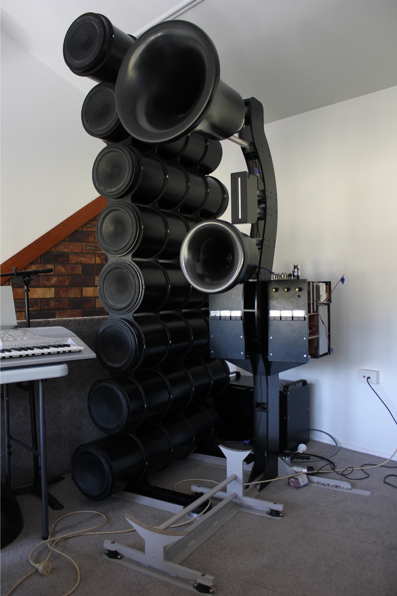
There was still a little soldering to do, speaker cables to attach, power cables to route, a few little last minute hiccups to solve.  I was so excited to just do it all then and there and light her up and listen that I did not trust myself not to overlook something, so I forced myself to wait.  Here and there over a couple of days I did the things necessary to fire her up until there came a moment when I had nothing left to do.

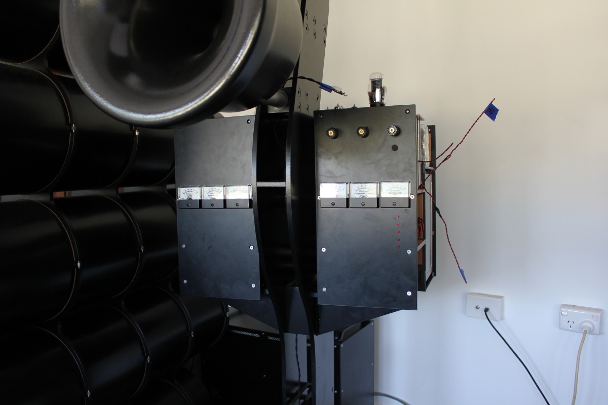
Below is how everything has been hooked up for the past twelve days...

DSET First Listening.jpg

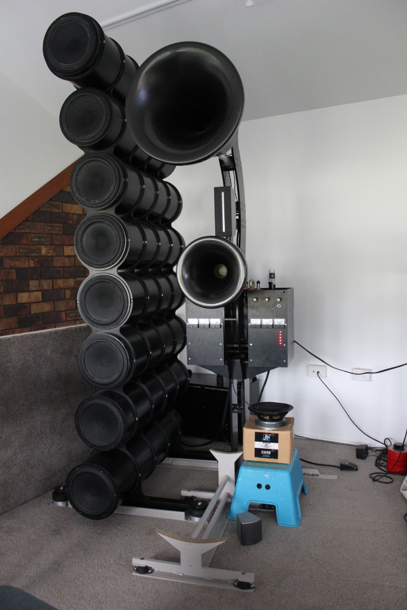
Still no Upperbass horn and the Fane 8M sitting as shown on its box on a stool.  Channel C is another of those tiny silver speakers that you can see in front of the blue stool, but it is turned down as far as the attenuation goes.  So with zero tuning or tweaking or aligning or other general care and consideration that one would expect is necessary for decent sound, and of course without the full complement of channels and missing perhaps the most important horn, I recorded the very first sounds to come out of my semi-assembled Macondo by playing a song called Reckless, which is very well known in Australia and is sort of appropriate given the way that I have thrown myself into this project.

Romy, I get the idea that you are not favourable about videos of sound being posted, but for me this was a milestone moment, and it was not horrible.  I can post the video of the very first sounds if you would like to hear them, just let me know.

In the past 12 days I have listened every day and probably have 80 hours on the amplifier and speakers.  I tried going back to the excellent standmounts that I had been listening to previously, but even in comparison to the incomplete mono Melquiades/Macondo they just miss so much...I could not stay listening to them.  Now that the valve current draws have stabilised and have been set at the recommended positions things are even more dire for the standmounts.  Briefly, I tried altering some operating current on the valves and now have a better understanding of how DSET can be used to shape the sound.  It is one thing reading about it but another thing entirely when you turn a knob on the amp and a particular portion of the sound changes...such a powerful tool.

Still Macondo is incomplete and there are sound issues around the bass and upperbass, but mids and highs are delightful.  I have performed some initial measurements towards room treatment for bass and the left Bass Cannon in its current position is flat to 18Hz in room, which is excellent, but I do have some work to do to get flatter in-room frequency response below about 150Hz, with some room modes from about 40Hz.  Some impromptu trapping made a good start towards this goal, so hopefully over coming months I will eventually have a suitable solution.

So I must say thank-you Romy, for your assistance and willingness and support so far.  At this stage I really think that the whole effort will be worthwhile and that I should end up with an acoustic system to keep me satisfied for decades.  At least the first sounds are very, very encouraging...   
03-02-2019 Post does not mapped to Knowledge Tree
Paul S
San Diego, California, USA
Posts 2,571
Joined on 10-12-2006

Post #: 163
Post ID: 25291
Reply to: 25290
Here's to You!
Another major milestone in a very big project, and looking great, by the way!

Best regards,
Paul S

03-02-2019 Post does not mapped to Knowledge Tree
Romy the Cat


Boston, MA
Posts 10,049
Joined on 05-28-2004

Post #: 164
Post ID: 25292
Reply to: 25290
Very commendable and noble job
 anthony wrote:
Briefly, I tried altering some operating current on the valves and now have a better understanding of how DSET can be used to shape the sound.  It is one thing reading about it but another thing entirely when you turn a knob on the amp and a particular portion of the sound changes...such a powerful tool.
I am not sure I agree with it. I do not see in Milq a great ability to altering some operating points. The driver stage is set, you can drive 25% more or less current of voltage but I do not feel that it changes sound very drastically. The same is with output stage. It does change very slightly the damping of the output stage. Well, I need to admit that the ScanSpeak array are very sensitive to dumpling, I have written about it before. A normal speaker is not so sensitive to damping so much. What I disagree is that altering operation point is a way use DSET. If you say “charge of the OTP sections for each channel then I would say YES, this is how you charge the damping. Not the changing of operation points. The objective of operation point is to set the tube foe symmetrical clipping, nothing else\. It means that for a max power of operation against the very specific load the top at the bottom sinusoid much clip at the same time. The top is current and the bottom is voltage (or wise versa, I do not remember now), you need to make sure that when they clip it will be symmetrical. DSET should clip by transformer, not by driver tube. From all that was said it is understandable that there is not a lot of operation point flexibility in a well designed amp.
 anthony wrote:
Still Macondo is incomplete and there are sound issues around the bass and upperbass, but mids and highs are delightful.  I have performed some initial measurements towards room treatment for bass and the left Bass Cannon in its current position is flat to 18Hz in room, which is excellent, but I do have some work to do to get flatter in-room frequency response below about 150Hz, with some room modes from about 40Hz.  Some impromptu trapping made a good start towards this goal, so hopefully over coming months I will eventually have a suitable solution.

Flat to 18Hz is a bit too god to be true. Not that I do not feel that it will not go down to 18Hz, this is well expected, but to be flat from 100 to 18… I would not believe in such a luck. I do not say imposable as I have seen it. Do not waste you time on trapping and the reset of it. Finish you upperbass, connect the things and I will let you know what sweep you need to post to calibrate the things properly. Do not fight with you room. This is bridge to nowhere. You your room imperfection if you have them as you expressive tools and factor the imperfections into the Macnondo sound. As you done with upperbass I will teach you how to do it. Without the upperbass there is no need to listen the Macondo. With the rest you have doe a very commendable and noble job.

Rgs,
Romy the Cat


"I wish I could score everything for horns." - Richard Wagner. "Our writing equipment takes part in the forming of our thoughts." - Friedrich Nietzsche
03-02-2019 Post does not mapped to Knowledge Tree
anthony
Posts 335
Joined on 08-18-2014

Post #: 165
Post ID: 25293
Reply to: 25292
Not exactly flat to 18Hz...
There are still room modes to contend with the first starting at about 41Hz.

Here is an impedance plot of the left Bass Cannon as seen by the amplifier, so including speaker cable.

DATS First Cannon (Left).jpg


As you can see I managed to get Fs down to about 44Hz and it turns out and an impedance range of about 1.1R to 3.15R, which apart from the unavoidable resonance peak is pretty flat from 5Hz - 1kHz.  Due to their dimensions I've had to use a very particular damping scheme of the Cannons to get this 'flatness'.  I also made quite an effort to seal up my room to get best use of 'room gain'.

The left Bass Cannon measured at the listening position in my untreated room gives the following graph:
Trapdoor Down, windows all closed.jpg


So not exactly flat, but conforming quite closely to expected room behaviour.  I am confident that I can greatly flatten those hills and fill those hollows and have run a few tests with just a couple of bags of wall insulation brought into the room and have had improvements in all of the hollows of up to 15dB and the peaks have come down a few dB each.  41Hz, is the biggest challenge, but I think I will be able to knock a fair bit from it without too much treatment.

The Upperbass Horns are still a ways from finished, but I am certainly trying to get them finished.  In the meantime I will work on the second DSET and perhaps take some measurements and give this first one a thorough check-over now that it seems to be reliable.

Regards,

Anthony  
03-02-2019 Post does not mapped to Knowledge Tree
Romy the Cat


Boston, MA
Posts 10,049
Joined on 05-28-2004

Post #: 166
Post ID: 25294
Reply to: 25293
Your bass is better then you music, be carefull...
Well, it might sound as a heresy to you, but I personally consider the impedance curve is a bit irrelevant in this application. In this application you need to care only about only 2 things: if you have enough power in you LF DSET to drive your line array and the character of sound in LF. If I was you I would keep lowering damping, more and more idling the LF output stage until you will be in danger the amp approaching clipping. They relies the damping a bit if you feel that you get too SS type of bass or THEN play with plate current to fine tune the damping.
 
The frequency response is another matter. You need one channel, no time-window and the mike in the exact listening position. I presume that your amps the drive bass has no filters. Your upperbass in your room might be running down to 100-120Hz. The 42Hz is not a problem at all. The problem as I see it is in the 65Hz suck out, but do not worry there are many ways to deal with it.  What I would like to do is to give me the individual swipe the topmost driver in the LF array and the lowest. They must have a deferent repose and I would like to learn the difference.
 
We will need the sweep for the other channel and the summation of the R and L channels. What filter you built in into the Milq’s Chenal A? Are you drive the bass now from the Milq’s full range channel? If yes then the Milq’s full range channel and A channel have VERY deferent damping characteristics…
 
PS: Man, you need to play better music with your playback. I am serious, it is very discouraging to hear you play crap music. Please if you want me not to be demoralized then fake better music interest in your videos.


"I wish I could score everything for horns." - Richard Wagner. "Our writing equipment takes part in the forming of our thoughts." - Friedrich Nietzsche
03-03-2019 Post does not mapped to Knowledge Tree
anthony
Posts 335
Joined on 08-18-2014

Post #: 167
Post ID: 25295
Reply to: 25294
I deserved that
 Romy the Cat wrote:
Well, it might sound as a heresy to you, but I personally consider the impedance curve is a bit irrelevant in this application. In this application you need to care only about only 2 things: if you have enough power in you LF DSET to drive your line array and the character of sound in LF. If I was you I would keep lowering damping, more and more idling the LF output stage until you will be in danger the amp approaching clipping. They relies the damping a bit if you feel that you get too SS type of bass or THEN play with plate current to fine tune the damping.
 

No, not heresy at all.

The impedance plot is important from the perspective that the Cannons are an unusual shape and prone to ringing because of that shape, which shows up in the impedance plot as well as when listening to them.  The ringing is gone, and I managed that by observing the impedance plot and listening to them at the prototype stage.  Nowadays, in the absence of outdoor SPL measurements to check frequency response the impedance info is the best available indicator of frequency response and other abberations because I am not pulling down a stack and taking the whole system outside just to measure the free-air response of the speakers...there is no need for that.

I will play with damping the 6C33C when the system is a little more mature.
  
 Romy the Cat wrote:
  
The frequency response is another matter. You need one channel, no time-window and the mike in the exact listening position. I presume that your amps the drive bass has no filters. Your upperbass in your room might be running down to 100-120Hz. The 42Hz is not a problem at all. The problem as I see it is in the 65Hz suck out, but do not worry there are many ways to deal with it.  


That SPL curve and the one that I include below is the entire left side Bass Cannon driven by Channel A of my DSET, no other drivers are connected.  At 1r nominal impedance I cannot drive it with any other channel or even my SS amps.  A first order, 60Hz low pass filter is included.  Mic is at the exact listening position

In the graph below you will see two lines:  blue is the empty room; brown/yellow is with the addition of two bags of polyester wall insulation (still in the bag) sitting in the corner behind the Bass Cannon being driven.

SPL Greenstuf 2 bags.jpg

...the 65Hz hole is more or less gone.  I think that upperbass hole can be filled reasonably well just with a little more room treatment.  The 40-55Hz stuff a little less easy but hopefully it will come together without too much effort with room treatment.

 Romy the Cat wrote:
 What I would like to do is to give me the individual swipe the topmost driver in the LF array and the lowest. They must have a deferent repose and I would like to learn the difference. 
  
We will need the sweep for the other channel and the summation of the R and L channels. What filter you built in into the Milq’s Chenal A? Are you drive the bass now from the Milq’s full range channel? If yes then the Milq’s full range channel and A channel have VERY deferent damping characteristics… 


I can give you the response of the top and bottom driver of the Cannons.  It is a fair bit of messing around not to unwire and measure but to wire the things back up...I have not left enough room for my fingers to easily get to the bolt, and wiring it up the first time took half and hour.

The rest of that stuff will need me to finish the second DSET and hook it up.  That will be a couple of weeks.

 Romy the Cat wrote:

PS: Man, you need to play better music with your playback. I am serious, it is very discouraging to hear you play crap music. Please if you want me not to be demoralized then fake better music interest in your videos.


Yeah, sorry.  It is a song from my childhood that I really loved at the time [and still do].  I am late to classical music...my parents are both country kinds of people but Mum still listens to a lot of older pop and a bit of jazz.  Would you believe that my interest in classical was seeded by very late night driving in my 20's where I would leave where I was working and drive 4 hours home through the rough and winding and almost non-populated hills and get in around midnight?  I would purposefully leave at about 8pm because that was when the friday night concert started on ABC Classic FM and it was listening to symphonic music in particular that kept me awake...complete engagement for hours and the trip was gone in the blink of an eye.

It has only grown from there.  If you have any suggestions for music please let me know.  I was thinking some Heifetz/Max Bruch Violin Concerto 1 that I discovered from the same FM station in my late 30's. 


03-03-2019 Post does not mapped to Knowledge Tree
Romy the Cat


Boston, MA
Posts 10,049
Joined on 05-28-2004

Post #: 168
Post ID: 25297
Reply to: 25295
Many variables in play
I do not care about the room treatment at this point. The treatment you use looks like very effective but it is very premature in my mind to think about it.  It is not to mention that the contribution the treatment has to LF frequency response is usually dubious as it frequently shorter reverberation time very unproportionable and more effective at upper bass then lower bass.  
 
What strikes me most is not you response, that might be worked anyhow, but rather the fact that you use your 60Hz low pass filter and you looks like do not have a good roll off. I was expecting that you upper knee of you LF will roll of much sipper. My tower with the very same drivers do decay much faster with the same filter. I do not know what cause of it. It might be enclosure that looks like “beaming” too much and the way how you room is you have no option to toe out your woofer tower away from you listening position. I am not sure it would be even effective at 200-400Hz…  
 
Anyway, you might consider going with second order in you bass tower. It is not something the you need to do now but keep it in your mind as an option. It would not be hard to do. The final design you will be making what you have your upperbass horn in place. You might use the decay of you woofer toward as some sort of pedal point that will have a foundation of your third octave, what they call drone, but your upper bass should ride atop as a alien dissonant harmony.  
 
The setting I describe above This requires some very precise tuning and no measurement will help you, you need to do it by ears.  You see, the sonic output of your woofer towers above 100H is very bad quality in my view. Hone is much more interesting, but it might not be “enough”. To run the woofer tower’s long tail is good way to beef up you above 100Hz but it needs to be done in proper balance. You run the woofer towers above 100Hz too hot, and you will make your very lower MF too impersonalized. If you run your woofer towers too shallow above 100Hz then you will use too sharp filter in you A-channel and you might lose some imaging at lower octaves. So, it is delicate game that you will need to play and ultimately you will make your own design based upon what you room can tolerate and demand.
   
Generally, I do not think you are ready now to think about it and there are other things that very much mask your ability to make the final decision about idiosyncrasies of LF and upperbass integration. Here is the methodologically proper sequence that I recommend.
   
1)    Make the speakers and amps fully operational.
2)    Use default Upperbass configuration
3)    Find an approximate LF configuration, not perfect but listenable, use digital crossover is fine at this point.
4)    Spend at least a week to listening and get comfortable with sound, not truly conformable but rather well familiar with the problem you have sub 500Hz, catalog the problem, literally write them down.
5)    Connect the upperbass horn to C channel (full range) and begin to play with volume and filter.
6)    Get the “feeling” how much you want the upperbass to ride over the LF
7)    Begin to fine tune your LF section
8)    After the LF is done then reapply that comfortable to you the “feeling” of upperbass to ride over the LF
   
When you begin to play with upperbass in my view the main dilemma that you need to decide for your is now to roll off the volume of the upperbass. You can do it with voltage divider at the “B” channel as I did in my case or you can do it by change the loading of output stage of your “B” channel. Unloading the output stage more will give you less distortions, faster sound, more transients, more dryness and less lash sound. It is not necessary too good but if you have the upperbass well supported by your LF at let say minus 8-9dB then you might like it. Eventually you will find the balance you like. I have found mine running the OPT in “B” configuration and burning some volume in resistors but you have a different OPT and different upperbass penetration by your lower bass. You might find a different configuration that you feel conformable.  
 
Also do not forget that I run now a dedicated midbass channel, it means the I felt that to have LF and upperbass was not enough…, but it was not enough ONLY in context of my current room… so as you see there are many variables in play…


"I wish I could score everything for horns." - Richard Wagner. "Our writing equipment takes part in the forming of our thoughts." - Friedrich Nietzsche
03-04-2019 Post does not mapped to Knowledge Tree
anthony
Posts 335
Joined on 08-18-2014

Post #: 169
Post ID: 25298
Reply to: 25297
I've got some work to do
Thanks Romy.  First the amps will be finished and then the Upperbass horns.  I may even get the second DSET ready to go upstairs this weekend assuming everything goes well and nothing goes wrong.  Will be nice to hear what I have at the moment in stereo.

A simple question:

Can you remember the thickness of the spacer between the Fane 8m and the Upperbass horn throat?  I have no idea what thickness is needed but I assume some kind of spacer is necessary to stop the surround striking the horn.  The back half of the horns are turned and I am thinking about fitting the drivers and the cover for the back chamber.

Regards,

Anthony


03-04-2019 Post does not mapped to Knowledge Tree
Romy the Cat


Boston, MA
Posts 10,049
Joined on 05-28-2004

Post #: 170
Post ID: 25299
Reply to: 25298
Some leads to explore.
 anthony wrote:
Can you remember the thickness of the spacer between the Fane 8m and the Upperbass horn throat?  I have no idea what thickness is needed but I assume some kind of spacer is necessary to stop the surround striking the horn.  The back half of the horns are turned and I am thinking about fitting the drivers and the cover for the back chamber.
Anthony, I have no idea, I did not build my upperbass horn and completely outsourced it to my builder. At that time I did not have a lot of experience with correlation of horn construction and sound and I had no particular opinion about the subject. I still have no my own practical experience to build horns and I the confidence that I excess sometimes on the subject come from talking not from doing the my own practical thin. If you would like some practical recordation, then talk to good reputed builders. Not all od then can corelate the building techniques with results. I very much Bruce Edgar and John Hasquin for instance. 

Bruce is very conditioned. He knows a lot have very highly reputed by my standards taste and but the solution that advocate is very much contingent upon the demand and character of his customers. Most of his customers are Mormons (like most people in audio) and when Moron need a solution from Bruce then he very much delegates the quality and complexity of his solution to very identifiable demands and understanding of his specific customer. If you however have good identity what you want and will dig Bruce deeper then a shallow surface then you can discover that his is a bottomless well of knowledge, practical experience and cultural class that you will handy ever will be able consume. So, if you jump in bed with Bruce then you will get a spectacular consulting.   
 
John Hasquin is an armature, it means the he does not make living by building horns but he made a lot of them and he is not a copromoting person, he can afford to shot for stars in anything he does. I absolutely love his judgment and his reasoning, he was BTW the guys who built most of my horns.   
 
There are many other guys out there who are interesting in horns building like Jeffrey Jackson, but they are more on professional side and I am not sure if they willing to spend their time for project of enthusiasts.  Bruce is very happy to consult horns enthusiasts, you can find him at AA’s High Efficiency forum. John Hasquin hangs around DIYAidio.com side.


"I wish I could score everything for horns." - Richard Wagner. "Our writing equipment takes part in the forming of our thoughts." - Friedrich Nietzsche
05-20-2019 Post does not mapped to Knowledge Tree
anthony
Posts 335
Joined on 08-18-2014

Post #: 171
Post ID: 25439
Reply to: 25299
Small steps
Unfortunately I've reached out but not managed to make contact with John Hasquin regarding the spacer in the upperbass horn.  I'll just have to wing it.

I did finally manage to get a day and a half to make the second DSET operational but it refuses to bias correctly.  I've traced the circuit a dozen times, checked component values, tried to find shorts, checked cap polarities, swapped tubes...no result.  The gas regulators both sit on 148v-149v with 15ma of current.  With the input shorted I am able to roughly bias the 6e5p/6e6p but a couple of channels only bias to -1.2V (Channel A & C), one to -2.2V (Channel B) and the rest are fine at -4V.  When I unshort the input I have 4.5V, yes volts, of DC offset, and the low bias tubes (A & C) actually swing into positive bias, which is strange.  Something is not right but I just cannot find it...a day and a half last weekend looking for it and I did not even turn on the soldering iron.  Very frustrating.  The fault will be found, I just need to be smarter about how I look for it...

So Romy, if you are able to offer any insight into how to find this fault I would be much appreciative.  I do understand that you will have much better things to do that hold my hand on this.

Anthony

PS:  The gogol suite cd arrived yesterday.  I'll rip it and see how quiet things are


05-21-2019 Post does not mapped to Knowledge Tree
Romy the Cat


Boston, MA
Posts 10,049
Joined on 05-28-2004

Post #: 172
Post ID: 25440
Reply to: 25439
Keep looking, I was there....:-)
 anthony wrote:
I did finally manage to get a day and a half to make the second DSET operational but it refuses to bias correctly.  I've traced the circuit a dozen times, checked component values, tried to find shorts, checked cap polarities, swapped tubes...no result.  The gas regulators both sit on 148v-149v with 15ma of current.  With the input shorted I am able to roughly bias the 6e5p/6e6p but a couple of channels only bias to -1.2V (Channel A & C), one to -2.2V (Channel B) and the rest are fine at -4V.  When I unshort the input I have 4.5V, yes volts, of DC offset, and the low bias tubes (A & C) actually swing into positive bias, which is strange.  Something is not right but I just cannot find it...a day and a half last weekend looking for it and I did not even turn on the soldering iron.  Very frustrating.  The fault will be found, I just need to be smarter about how I look for it...
So Romy, if you are able to offer any insight into how to find this fault I would be much appreciative.  I do understand that you will have much better things to do that hold my hand on this.
 Anthony, unfortunately I have no time now to look into it deeper and I assure you that unit I will you will find the fix on your own. There is something that you did wrong of one of you component is faulty. The best way to fine it is to roll the complexity back, to isolate the channels and to test them independently. Take the circuit and write the voltages that should there before and after of each element in the channel, then measure the actual voltages. You will very soon find the location where the inconstancy took place.


"I wish I could score everything for horns." - Richard Wagner. "Our writing equipment takes part in the forming of our thoughts." - Friedrich Nietzsche
08-21-2019 Post does not mapped to Knowledge Tree
anthony
Posts 335
Joined on 08-18-2014

Post #: 173
Post ID: 25551
Reply to: 25440
Still no stereo
Yes, the second DSET is still not biasing properly and I cannot find enough consecutive time to look for the fault.  In the meantime I've got a couple of minor side projects off the electronics bench, and started thinking seriously about preamplifiers.  Part of the thought process is to do with analogue volume controls and to make some decent decisions I need to know the input impedance of the DSET's.  So I measured it...see below.

DSET Input Impedance 2V Pink Noise FFT.png


Romy, the back-of-the-envelope estimation of about 5k Zin is roughly correct.  You can see in the graph above that at 20K Zin gets as low as 3.5k.  Phase is flat until the inductors kick in circa 600Hz, 3.2kHz and 10kHz which causes it to roll off or less linearly with frequency.

08-21-2019 Post does not mapped to Knowledge Tree
Romy the Cat


Boston, MA
Posts 10,049
Joined on 05-28-2004

Post #: 174
Post ID: 25552
Reply to: 25551
Good luck... :-)
 anthony wrote:
Yes, the second DSET is still not biasing properly and I cannot find enough consecutive time to look for the fault.  In the meantime I've got a couple of minor side projects off the electronics bench, and started thinking seriously about preamplifiers.  Part of the thought process is to do with analogue volume controls and to make some decent decisions I need to know the input impedance of the DSET's.  So I measured it...see below.

Romy, the back-of-the-envelope estimation of about 5k Zin is roughly correct.  You can see in the graph above that at 20K Zin gets as low as 3.5k.  Phase is flat until the inductors kick in circa 600Hz, 3.2kHz and 10kHz which causes it to roll off or less linearly with frequency.
   
Anthony, I know about the shortage of “enough consecutive time”. I am in the same boat here… I think that fact that you took some time off is good for debugging, what you come back to it you will find what you connected wrong. It is most like one of the emails of the filter you connected to the wrong point. You juts need to fine where it is. When you have time to go back to it then write up the voltages and we can go over it together again.
The impute impedance of 5K is was very predictable, 5 line of 30K in parallel. The drop of the impedance at HF is irrelevant in my view as damping at HF is not so effective. If you do not have low enough out impedance at your sored then the whole character of lower octaves get screed and it is very auditable. Also, you filter will not work properly. The thinking seriously about preamplifiers is hard and frankly you are at your own. I still cannot fathom why Placcete does not work in you case, but it is what it is. All that you need to have a good buffer + gain that can drive current and have as low impedance as possible, DC coupled would be the best, or the simplest to archive the lowest impedance. If I were you then I would not build but try a few of the shelf cortical preams. It is not that you need to buy them but going over the trails with commercial pros you will develop an acquired taste of what you need. Also, some of them might be good for you. Do what I did: connect a few manufactures, give them the specification you need and see what they will offer to you. Most of the manufactures if they see an unusual and original need will bypass the worthless dealers and will work with you directly. Some small makers will even do some custom work for you… 
 
Anyhow, it is hard to find a good pream generally and the one that can drive a couple kOm in particularly. There are a lot of options out there, do not re-invent, adapt and improve, unless you are in a driving sit and know what and how to do the thing and how to evaluate/interpret the results properly. The last one is tricky and you need to know you own playback VERY well to decipher and discriminate the preams contribution. It took for me years to learn it and I am still not immune from mistakes.


"I wish I could score everything for horns." - Richard Wagner. "Our writing equipment takes part in the forming of our thoughts." - Friedrich Nietzsche
08-22-2019 Post does not mapped to Knowledge Tree
anthony
Posts 335
Joined on 08-18-2014

Post #: 175
Post ID: 25553
Reply to: 25552
I've not given up...
...on the Placette.  Biggest problem at the moment is that it does not have any gain and I definitely need some gain.

What I have done is breadboarded a nice diy SS pre with 2x or 3x gain, dc coupled, current mirror, 100mA.  It was started a couple of years ago and set aside.  The output impedance has long been forgotten, but I can measure it.

A local guy, Clay Gieseler, makes some really well engineered SS amps, dacs, and preamps and I picked up a used pre of his design.  It sounds really good, I like it.  Perhaps that is just the extra volume, but nonetheless I like it.  Change a couple of resistors to increase the gain a little more and it may be a keeper apart from the fact that it has only three inputs...Clay might be able to be convinced to make me a new one with more inputs.  The VC is based on the Muses chip and sounds very promising.

Winging it's way to me shortly is a low noise, low thd, small, well engineered Gain Block One which is a simple SS gain stage made by Tasmanian Anthony Holton who is best known for his diy products and commercial SS amplifiers.  It is DC coupled also and may be combined with a VC and input selector to make a preamp or perhaps used as a gain stage in the Placette thus making use of its excellent VC.  This is more or less what Guy Hammel would supply and what you are using.  Just whether or not it is best solution for me will be seen, it may best be used on its own.

On top of this, I have ordered parts to experiment with building some single stage DHT preamps.  These can be prototyped quickly without wasting too much time.  There are certain metrics that the preamp has to meet regarding low distortion, output impedance, current, noise etc. and if they don't meet them on the prototype then I won't put them in a case and keep them.  I've been warned that the approach I am taking in the design may make them sound solid state, but that is really what I (think I) need, and there are really only a few ways these amps can be designed such that they will meet all the metrics while maintaining enough gain.

The whole process will be interesting, and I will learn a heap.  Right now I wouldn't be game to guess which solution I will end up using, if any of these.
Page 7 of 8 (187 items) Select Pages:  « First ... « 4 5 6 7 8 »
Home Page  |  Last 24Hours  | Search  |  SiteMap  | Questions or Problems | Copyright Note
The content of all messages within the Forums Copyright © by authors of the posts