Rerurn to Romy the Cat's Site

Audio Discussions
Topic: Correcting Filters and the quantum theory.

Page 1 of 1 (4 items)


Posted by Romy the Cat on 09-06-2008

Ok, can somebody to elaborate on the judgment which filter is better in case it is a corrector that acts in the middle of auditable range, let say from 1000Hz? It is the same filter but let look at the theory of judgments.

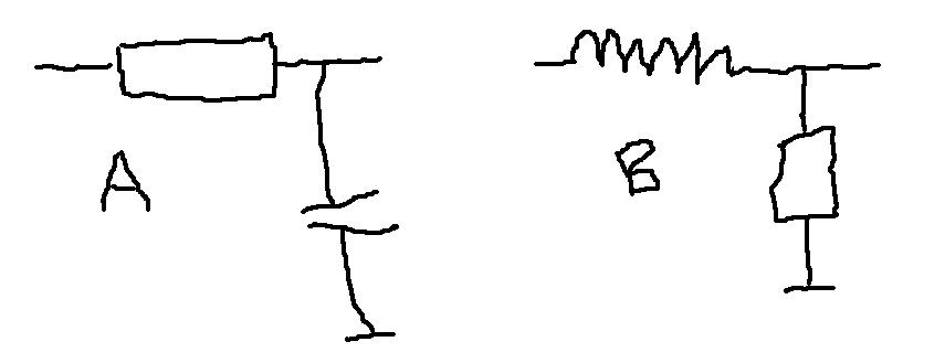
1)      Filter A is conceptually better because it acts as shunt filter, kind of subtraction corrector… The signal in band-pass (below 1000Hz ) does not see filter at all and whatever is being filtered out is shunted to ground. Therefore the signal that is passing through does not exposed to the nastiness of capacitor’s dialectic.

2)      Filter C is conceptually better because “indictors are better” and there is no transmission line reflections form the capacitor’s dialectic like in the filter A. The fact that the band-pass signal below 1000Hz flows unnecessary through the 120 feet of copper in the coil is irrelevant.

3)      It is all depend of the quality of coil and the quality of capacitor and if both of them are conceptually “perfect" then there is no difference.

I would like to hear your take, not just the take but also your justifications

Thanks, the Cat

Posted by hagtech on 09-07-2008
My first answer would be "3".  But then I think some more...

Is "A" really a shunt?  Where is the power dissipated?  Certainly not in the capacitor.  The signal is burned off (converted to heat) in the series element!  In circuit "B" it is the shunt element that burns off the power above 1kHz.

Why is an inductor better?  It has permeability issues (akin to permittivity in a dielectric), magnetic hysteresis, interwinding capacitance, etc.

When investigating questions like this I often take things to the extreme.  For example, what if the input signal was a kilovolt?  Now you think about volts per meter and insulation and arcing through the atmosphere and humidity and electrode spacing of the capacitor and heat dissipation in the resistor.  What if the frequency was 1GHz?  What if the frequency was 0.1Hz?  That coil starts to get pretty big.  What practical issues show up at the extremes?  Now re-apply them to the question at hand.  All the things one has to worry about at the extremes are still existent at 1 volt and 1kHz, just to a different degree.  But it does get you to think about theoretical limitations.

The other thing is that you can never appropriately ask such a question in isolation.  The circuitry before and after this filter changes the reality.  Often, the answer is more dependent upon the driving or receiving circuits than anything else.

So I guess I stick with "3" for now.

jh

Posted by CO on 09-14-2008
Filter B will have equal damping of the driver for all frequencies while setup A has "none" until the cap is full.

Posted by Romy the Cat on 10-05-2008
I got a pair of good Pultec shielded coils that I am planning to stick in the Rohde & Schwarz’s multiples decoder to replace the Schwarz’s original RC based 75ms FM de-emphasis. I still am contemplation if to stick the filter in open loop where the signal would flow across the coil or to use the subtraction filter in feedback what the filter will be shunting and the signal would not flow across a few dozen feets of the coils’ wire.

R&S_decoder_output.jpg


Page 1 of 1 (4 items)